System, method, and apparatus for providing a thermal bypass in electronic equipment

a technology of electronic equipment and thermal bypass, which is applied in the field of system, method and apparatus for thermal bypassing selected components of electronic equipment, can solve the problems of achieve the effect of bypassing the subsystem, reducing the temperature of electronic circuitry, and reducing the cooling capacity of airflow

Active Publication Date: 2006-11-14
INT BUSINESS MASCH CORP
View PDF6 Cites 42 Cited by
  • Summary
  • Abstract
  • Description
  • Claims
  • Application Information

AI Technical Summary

Benefits of technology

[0016]One embodiment of a system, method, and apparatus for lowering the temperature of electronic circuitry in situations where the circuitry is thermally “downstream” of other hot components is disclosed. The airflow reaching the downstream circuitry has passed through other upstream components and has been pre-heated, thereby reducing the cooling capacity of the airflow. The present invention works by removing heat from the incoming or ambient airflow and transferring the heat directly to the outlet airflow of the subsystem, thereby effectively bypassing the subsystem in a thermal sense.
[0017]The present invention teaches that a thermoelectric cooling (TEC) module may be combined with heat exchanger elements and positioned in such a way that the incoming air entering a subsystem may be cooled and the extracted heat may be transferred directly to the exhaust of that subsystem through the TEC. While not greatly affecting the final exhaust temperature of the enclosure, the invention allows localized cooling within a portion of the enclosure, from which the downstream subsystems may greatly benefit. The present application of TECs is also easily differentiated by noting that the invention involves a single airflow that is cooled at one point and heated at another point in such a way that some of the heat in the air effectively bypasses a portion of the flow path.

Problems solved by technology

The airflow reaching the downstream circuitry has passed through other upstream components and has been pre-heated, thereby reducing the cooling capacity of the airflow.

Method used


Image

  • System, method, and apparatus for providing a thermal bypass in electronic equipment
  • System, method, and apparatus for providing a thermal bypass in electronic equipment
  • System, method, and apparatus for providing a thermal bypass in electronic equipment

Examples


Embodiment Construction

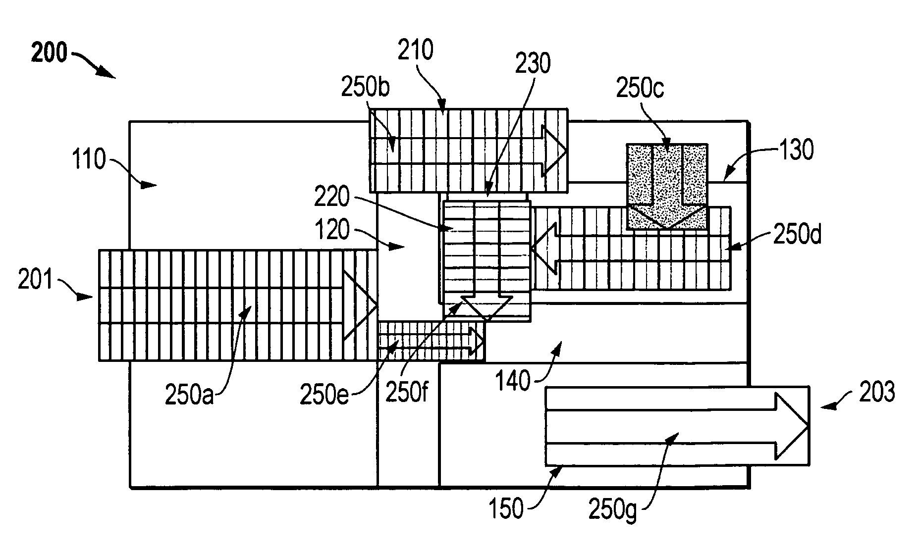
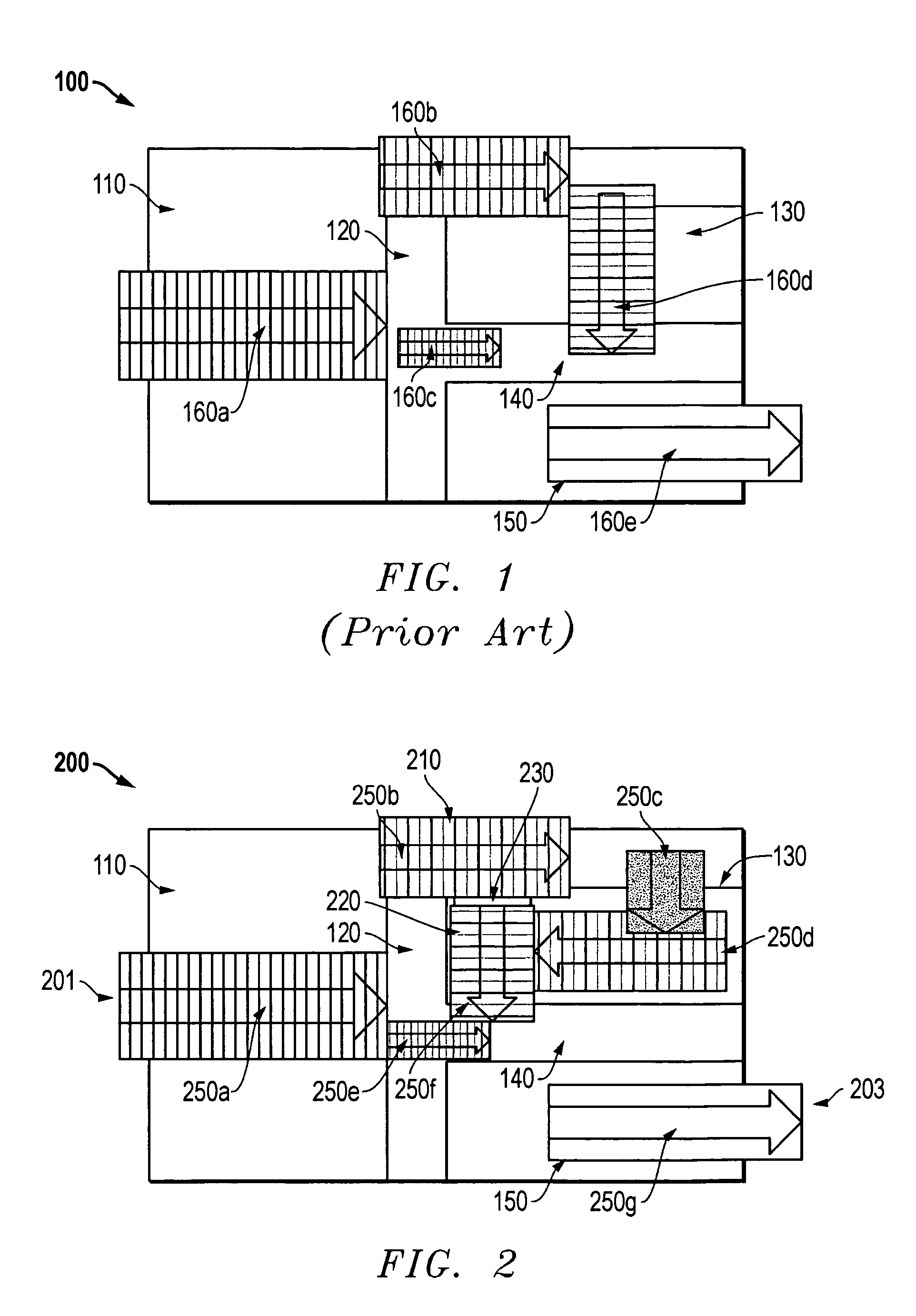
[0029]Referring to FIG. 2, one embodiment of a system, method, and apparatus for thermal management in an electronics environment is shown and constructed in accordance with the present invention. In the embodiment illustrated, the present invention is configured with a first heat exchanger 210, a second heat exchanger 220, and a thermoelectric cooling (TEC) module 230. Air 250 enters the system enclosure 200 through an ingress or front entry 201 and is heated or “pre-heated”250a by server blade(s) 110. The airflow may split into a portion 250b that travels to a section (e.g., the top) of the system enclosure 200, and a portion 250e that finds other paths to the final plenum.

[0030]In accordance with the present invention, air destined for the network switch 130 or other subsystem(s) has some heat removed 250b by passing by or through the first heat exchanger 210. The heat exchanger 210 is coupled to or in contact with the cold side of the TEC module 230. The air temperature of this ...


PUM


Abstract

A system enclosure uses two heat exchangers and a thermoelectric cooling module to manage heat within the system. An airflow enters the system and is heated by server blades. Portions of the airflow split and travel to various portions of the system enclosure. Some heat is removed from the airflow by passing through the first heat exchanger before circulating around downstream subsystems. The first heat exchanger contacts the cold side of a TEC module, to reduce the temperature of that airflow. The air then enters the network switch module or other subsystem where it is further heated. Thereafter, the second heat exchanger ‘bypasses’ those components by reinserting the upstream heat back into the downstream airflow. The second heat exchanger contacts the hot side of the TEC module. The mixture of all heated air is then expelled from the system enclosure.

Description

BACKGROUND OF THE INVENTION[0001]1. Technical Field[0002]The present invention relates in general to an improved thermal management design and, in particular, to an improved system, method, and apparatus for thermally bypassing selected components in electronic equipment.[0003]2. Description of the Related Art[0004]It is well known in the industry that heat contributes to early failures of electronic equipment. As processor clock speeds and rotational speeds of magnetic media increase and the number of processors used in some systems (e.g., servers) increases, heat becomes even more of an issue. In some designs it is necessary to use air that has already passed over hot components to cool other components that are further “downstream” with respect to the airflow.[0005]For example, in IBM's BladeCenter™, air enters a frontal enclosure, passes numerous server blades, then passes through network switch modules, management modules, and power modules before finally being drawn out of the...

Claims


Application Information

Patent Timeline
Patent Type & Authority Patents(United States)
IPC IPC(8): F25B21/02F25D23/12H05K7/20
CPCH05K7/20F25B21/02F25B2321/0251
Inventor CRIPPEN, MARTIN JOSEPHMATTESON, JASON AARONPIAZZA, WILLIAM JOSEPH
Owner INT BUSINESS MASCH CORP
Why Eureka
Try Eureka