Apparatus and system for concentrating slurry solids

a technology of concentrating apparatus and slurry, applied in the field of separation solids, can solve the problems of significant capital and operational costs of processing slurry using centrifuge-based systems, known but expensive methods for mechanical separation solids, and relatively low efficiency, so as to facilitate the buildup of solids mass, reduce capital and operational costs, and reduce the effect of rig down tim

Inactive Publication Date: 2006-11-14
PALMER ROBERT M
View PDF20 Cites 35 Cited by
  • Summary
  • Abstract
  • Description
  • Claims
  • Application Information

AI Technical Summary

Benefits of technology

[0033]A novel apparatus, being a conical tank having an inlet above and substantially co-axial with a solids outlet below, is used to create and maintain a “plug” that is a concentrated mass of solids over the solids outlet to minimize water escaping through the solids outlet once the system of the invention reaches steady-state operation. Concentration results directly from the increased pressure of a moving mass of solids accelerating (either propelled or in free-fall) towards the solids outlet from the inlet. Concentration is enhanced by using a conduit that maintains a stack of solids over top of the solids outlet. The conduit (that is typically cylindrical but may be of any cross-sectional shape) advantageously acts secondarily as a baffle member providing residual separation if required. The combined effect of pushing the components separated from the slurry towards the outlet and stacking the solids in a substantially conical body above the outlet (enhancing the static head), is to deliver a more dense mass of solids to the centrifuges while displacing fluids upwards where the fluids may be drained out, skimmed off, or sucked away from the tank without ever reaching the centrifuges.
[0044]The system and method of the present invention immediately directs the slurry towards the tank outlet in order to minimize the time that solids spend in the concentration tank. In order to overcome the disadvantages of the prior art it became important to concentrate the separated solids over the tank outlet to displace water from entering the centrifuges. Advantageously, using baffles to aggressively direct solids to the outlet and minimize the time that solids spend in the concentration tank, a higher average system capacity is achieved, together with reduced utilization of fresh water, flocculating chemical, and centrifuges.

Problems solved by technology

A known but expensive method for mechanically separating solids from drilling fluid, which is employed in '053, is to pass the slurry through a centrifuge.
The capital and operational costs of processing slurry using a centrifuge-based system are significant because large capacity units are expensive and consume large quantities of electrical power, which power is not always available at drilling sites.
'053 also teaches baffles used in the traditional manner (to interrupt and slow the movement of slurry) installed in an elongate “settling tank” having a large open trough and auger extending substantially its entire length along the bottom of the tank; disadvantageously, the relatively large opening and the mixing action of the auger of '053 tend to allow access by substantial amounts of water from the tank to the solids outlet as well as agitating the solids and blending them with further excess water.
The failure to prevent or reduce the amount of water reaching the centrifuges causes a relatively low efficiency due to excess water circulating through the centrifuges reducing the mass of solids being processed during a period of operation.
Disadvantageously, this passive distribution of solids permits substantial water to be drawn from the settling tank into the centrifuge where power is consumed in mechanically separating excess water from solids.
Disadvantageously, this design is limiting in its throughput and necessitates the use of devices for removing solids from the tanks.
Disadvantageously, the larger the outlet the more difficult it is to prevent the liquids from entering the solids outlet.
Further, to maintain the physical concentration ratios of flocculant to entrained solids when slurry is pre-treated with a flocculating agent, many such systems unintentionally re-circulate water that has already had solids removed, thereby wastefully processing the same volumes of water more than once.
Disadvantageously, these designs rely on separation occurring within the tank and use baffles in the traditional manner for separation.
The fluid outlet of '554 is at the top of the tank using a bowl collector to drain off clean water, but which bowl disadvantageously interferes with access to interior portions of the tank such that no baffles are employed inside the tank.
Consequently, any concentration in these settling tanks is merely incidental to the collection of solids during separation.
The baffles extend the time that the slurry blend remains inside the tank by extending the length of the path between the inlet and outlet of a settling tank, however the effectiveness of such separation drops as the slurry processing rate increases beyond the capacity of mechanical separators.

Method used


Image

  • Apparatus and system for concentrating slurry solids
  • Apparatus and system for concentrating slurry solids
  • Apparatus and system for concentrating slurry solids

Examples


Embodiment Construction

[0055]Reference is now made in detail to FIGS. 1–8, in which identical reference numbers identify similar components.

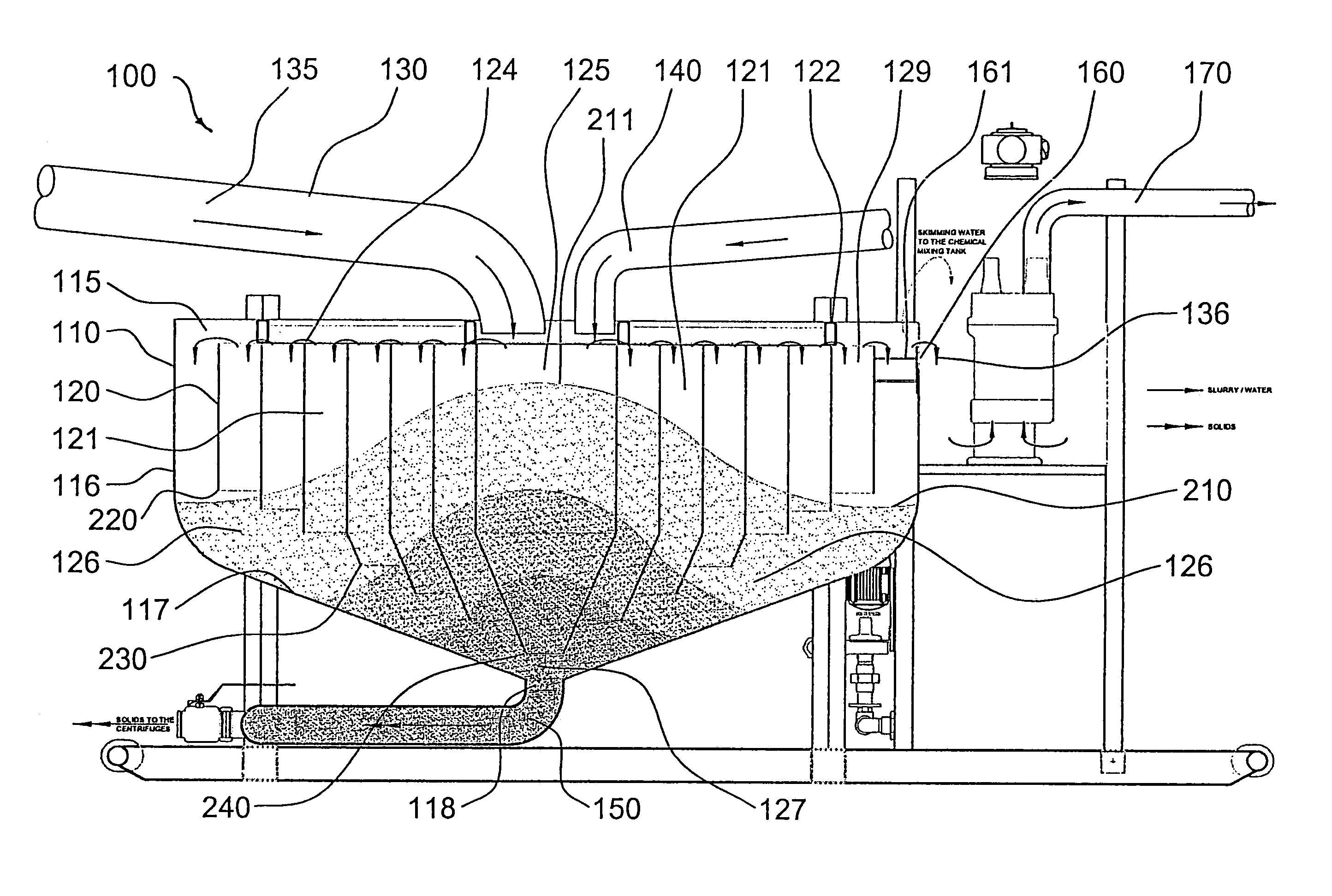
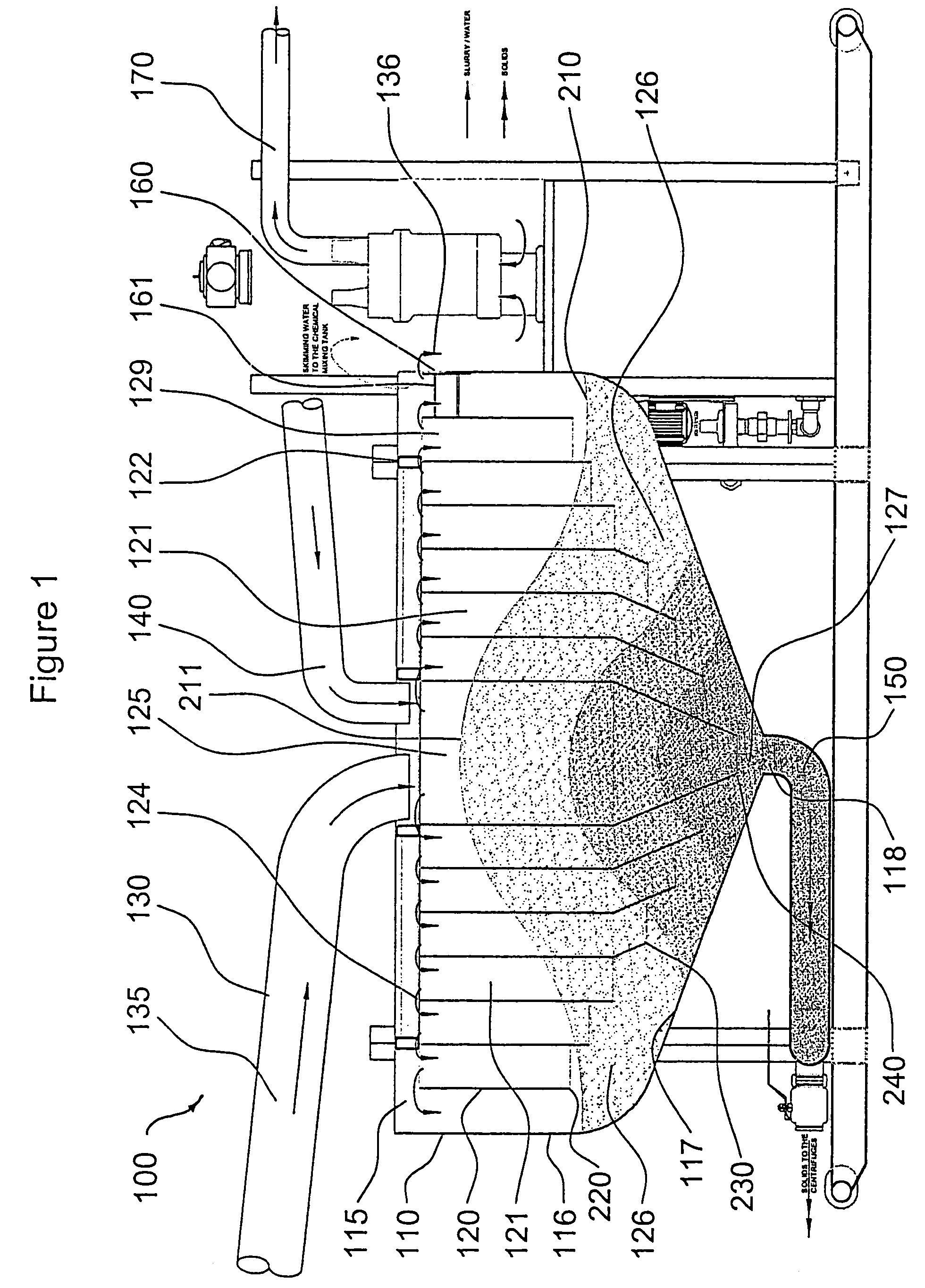
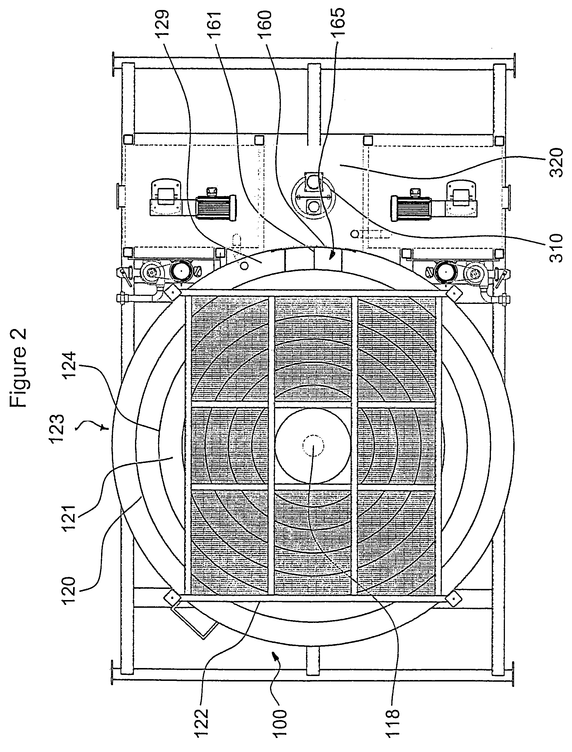
[0056]Referring now to FIGS. 1–5, there is illustrated a preferred embodiment of an apparatus denoted generally as 100 comprising a concentration tank 110 having an inlet 115, sidewalls 116, a conical base 117, an outlet 118, baffles 120, chambers 121, fluid return 140, exit conduit 150, and at least one skimmer or drain 160. On start-up, apparatus 100 is filled with water (not shown) and centrifuges (not shown) may be operated to create suction at outlet 118. A stream of pre-flocculated slurry 135 enters tank 110 from conduit 130 through inlet 115 directly into central chamber 125 where the slurry drops towards bottom space 127 of tank 110 at a volume per unit time sufficient to fill outlet 118 and then backup along annular passage 126 until tank 110 is substantially filled with slurry displacing the water with which it was filled on start-up. In the course of displa...


PUM

PropertyMeasurementUnit
mass densityaaaaaaaaaa
massaaaaaaaaaa
conical massaaaaaaaaaa

Abstract

An apparatus to separate solids from drilling slurry, having an inlet positioned over an outlet of a concentration tank to displace water that would otherwise enter the down-stream centrifuges. Baffles are provided to direct solids to the outlet and minimize the time that solids spend in the concentration tank. Fluids having solids removed therefrom are removed from the apparatus at a location remote from the outlet.

Description

FIELD OF THE INVENTION[0001]The present invention relates generally to separating solids out of a liquid / solid mixture, and more particularly to methods and equipment for separating cuttings from drilling slurry.BACKGROUND OF THE INVENTION[0002]Canadian Patent 2,219,053 to Rowney (“'053”) teaches that wells for oil, gas and the like are typically drilled by a rig that includes a hollow drill string with a bit at its lower end. As the drill string is rotated, drilling fluids are pumped down through a channel in the drill string. The drilling fluids pass through the bit and return to the surface (as a slurry) on the outside of the drill string, carrying cuttings to the surface where the drilling fluids are recovered and recycled. Water may be used as drilling fluid in shallow drilling, but in deeper wells drilling “muds” of various compositions are used. Cuttings and other undesired solids are separated from recovered drilling fluids before re-use of the drilling fluids. A known but e...

Claims


Application Information

Patent Timeline
Patent Type & Authority Patents(United States)
IPC IPC(8): B01D21/01B01D21/08B01D21/00B01D21/26C02F1/52E21B21/06E21B43/34
CPCB01D21/0045B01D21/0054B01D21/01B01D21/2427B01D21/2444B01D21/2488B01D21/26B01D21/34E21B21/065B01D21/0069B01D21/0024B01D2221/04
Inventor PALMER, ROBERT M.
Owner PALMER ROBERT M
Why Eureka
Try Eureka