Method and device for determining the angular inclination of a shaft in a rotating machine

a technology of rotating machines and shafts, which is applied in the direction of measuring devices, converting sensor output electrically/magnetically, instruments, etc., can solve the problems of fuel consumption, misfiring, and negatively affecting the working life of combustion engines, so as to improve fuel economy, accurately and accurately determined, the effect of regulating

Inactive Publication Date: 2006-11-14
ABB (SCHWEIZ) AG
View PDF11 Cites 11 Cited by
  • Summary
  • Abstract
  • Description
  • Claims
  • Application Information

AI Technical Summary

Benefits of technology

[0024]The advantage of the invention is that the position of a gear tooth of a gear wheel may be rapidly and accurately determined. This means that the inclination of a shaft on which a gear wheel is mounted on may be determined accurately and quickly enough to regulate, for example, the combustion characteristics of an internal combustion engine while it is running. This in turn means that improved fuel economy may be obtained as well as close control over exhaust emissions. Relatively small savings in fuel and improvements in exhaust composition in percentage terms as a result of improved engine control produce a great benefit in fuel savings and in exhaust gas emission improvements when taken over the whole operating life of an engine.
[0025]The present invention is also efficient in operation as it comprises non-moving parts only and requires almost no maintenance. The detection system is not affected by wear, dirt or corrosion of the gear teeth. It is also not affected by changes in the relative shape of one or more gear teeth as it is the centre point to the gear tooth that is detected. Thus the method may be used throughout the service life of the engine. A common problem with earlier attempts to use inductive measurement of gear tooth position was that the material parameters of the gear tooth, such as electrical resistivity and magnetic permeability, had an affect on the way that a signal changed over time. Even in the event that material parameters vary across one and the same gear tooth, a device according to the present invention will still measure mid position correctly. Because the integration time according to the above is short, as mentioned above, it is only the gear tooth surface and size that is measured and not the effect from material parameters, and thus it is not significant for precision of the measurement if material parameters vary over the surface.
[0026]The invention may be applied very widely to any motor, old or new.
[0027]Other uses for the present invention include the measuring fixed positions of metal objects on a conveyor belt or similar devices, as well as measuring the position of an arm arranged with a regular pattern of metal parts.BRIEF DESCRIPTION OF THE FIGURES
[0028]A more complete understanding of the method and apparatus of the present invention may be had by reference to the following detailed description when taken in conjunction with the accompanying drawings wherein:
[0029]FIG. 1 shows schematically a preferred embodiment according to the present invention;

Problems solved by technology

Misfiring influences exhaust gas chemical composition, fuel consumption, and can also negatively influence the working life of a combustion engine.
Misfiring influences exhaust gas chemical composition and can also negatively influence the working life of a combustion engine.
Such a method may only be applied when there is a length of shaft available where angular measurement is desired, rather than a shaft that is built-in or enclosed an impractical to reach.
If one then wishes to measure the position of the shaft at a certain point, the twist up to the end of the shaft may be so great that it introduces serious errors in the measurement if the position of the end is measured.
Such devices have shown themselves to function well in clean environments but have difficulties in dirtier surroundings.
Furthermore, it has been difficult to attach such devices in a satisfactory way to large machines with powerful vibrations and great mechanical forces.
It has been difficult to achieve better than relatively low accuracy with these devices even though the desired accuracy required for regulation of the adjacent apparatus is high.
Such devices have not come into as widespread use as has been desired.
The low accuracy of these devices depends on that the signal they give is not only dependent on the position of the gear tooth, but also of the appearance of the gear tooth, the distance between gear tooth and measuring device and the magnetic characteristics of the gear tooth.
A difficulty with this measurement device is to determine position of an object being measured when distance to or shape of the object is changed.
In the same way the edge position of a gear tooth could be measured but a problem with that device is that extensive mathematical calculations are demanded, which leads to a problem with time when used with a rapidly rotating gearwheel.
Moreover the calculations demand fast computing capacity, which could make such a device unnecessarily costly in order to measure the position of a gear tooth.

Method used


Image

  • Method and device for determining the angular inclination of a shaft in a rotating machine
  • Method and device for determining the angular inclination of a shaft in a rotating machine
  • Method and device for determining the angular inclination of a shaft in a rotating machine

Examples


Embodiment Construction

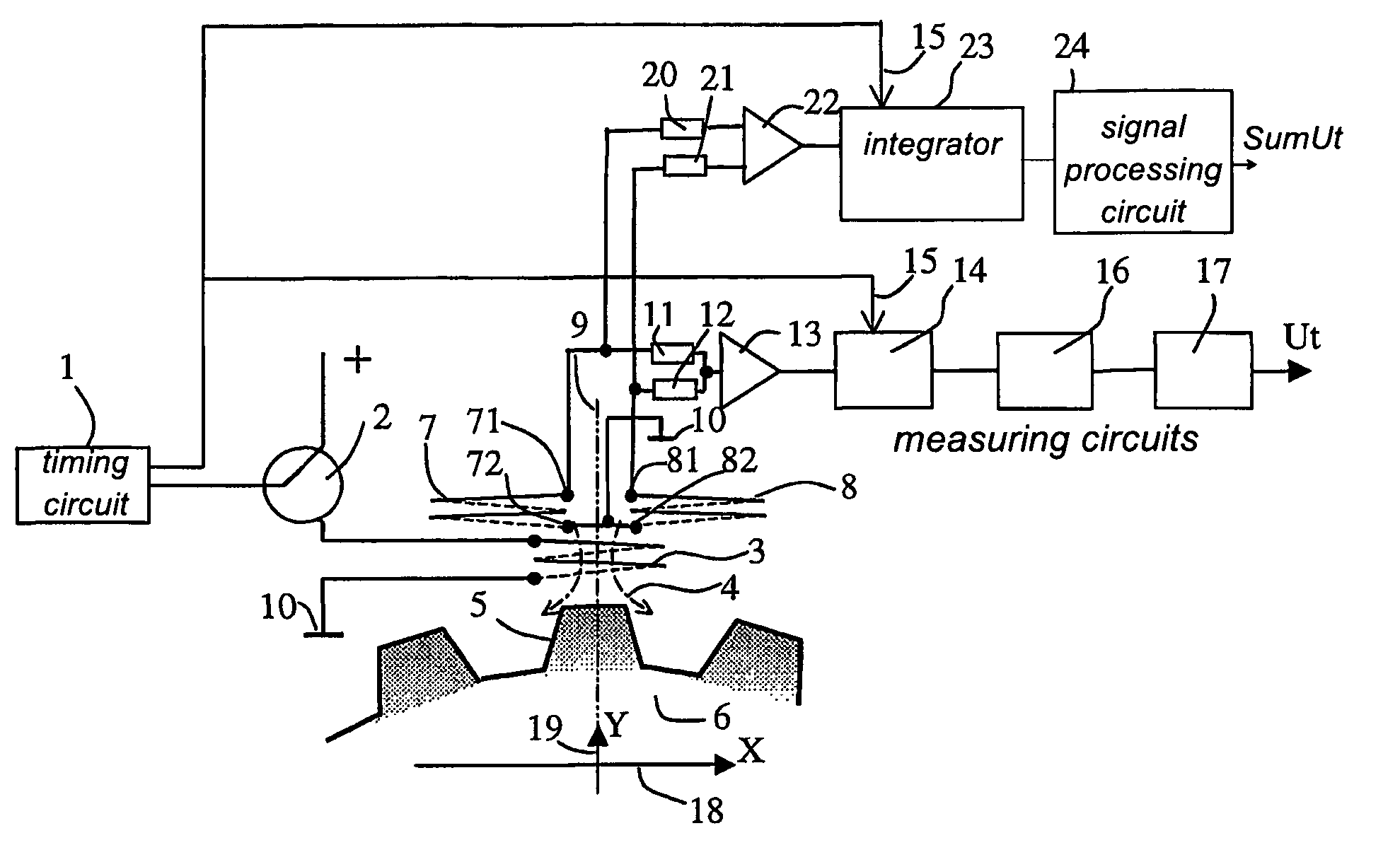
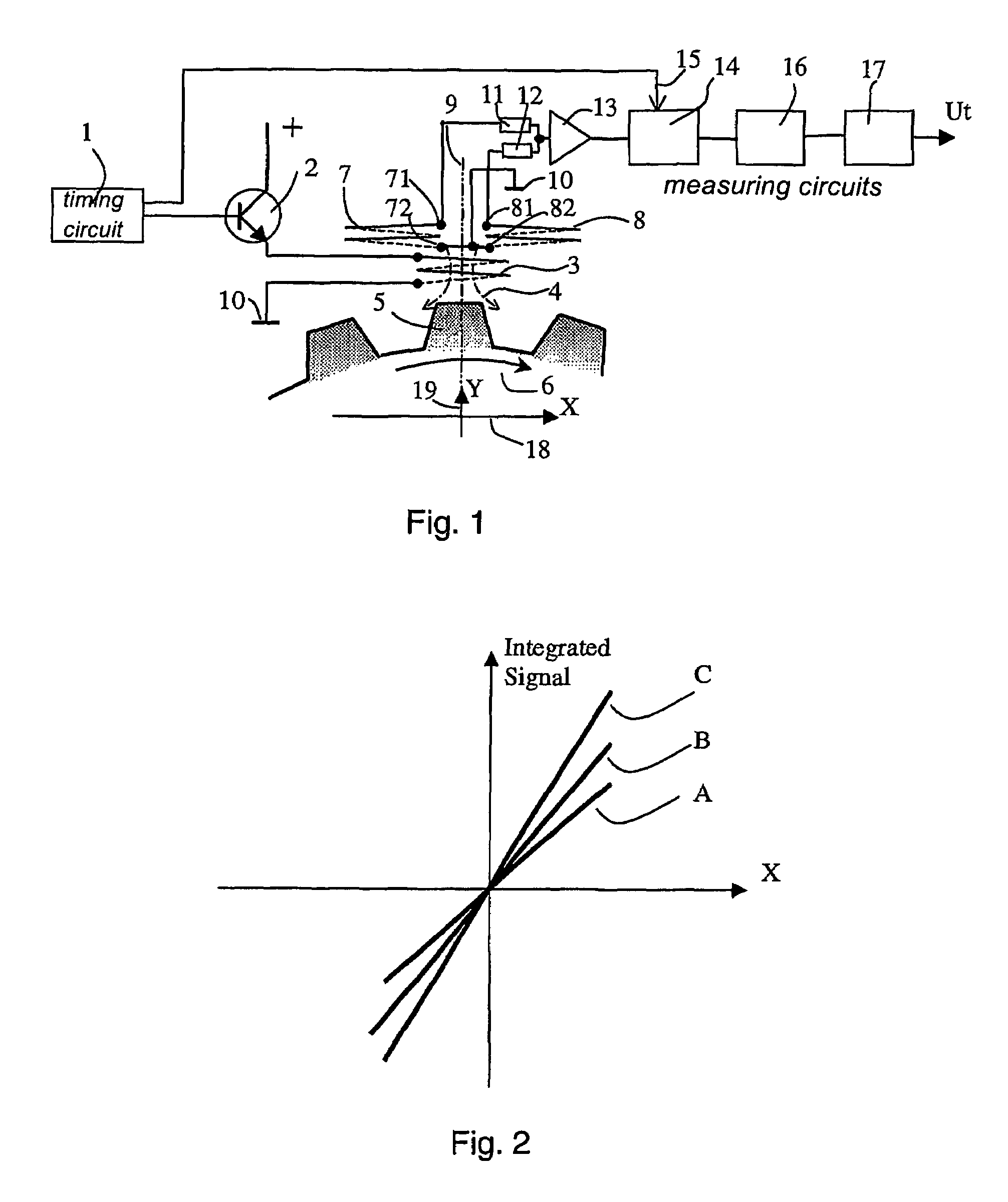
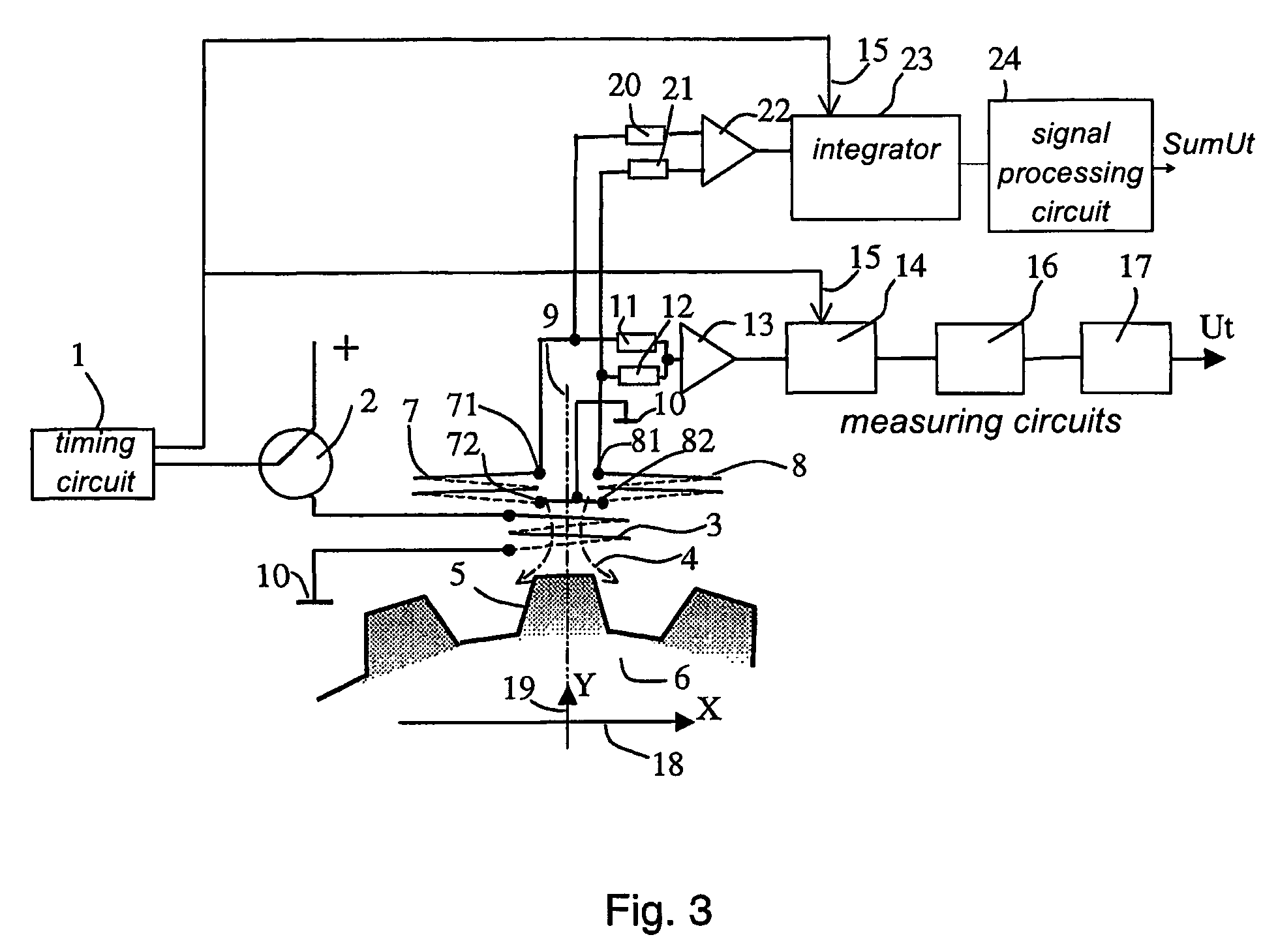
[0034]FIG. 1 shows a gear tooth 5 on a gear wheel (not shown) rotating in a direction shown by arrow 6. A transmitter coil 3 and two receiving coils 7, 8 are arranged in a position relative to gear tooth 5. A timing circuit 1 is electrically connected to a transistor 2, which is further is connected to transmitter coil 3. One end of transmitter coil 3 is also connected to earth 10. Receiving coils 7, 8 are placed symmetrically about an axis of symmetry 9 of the transmitter coil 3. Receiving coils 7, 8 are connected to earth 10 or a defined potential through ends 72, 82. The receiving coils 7, 8 are each connected through their other ends 71, 81 via resistances 11, 12 to an amplifier 13, an integrator 14, a circuit 16 arranged to measure an integrated signal and another circuit 17 arranged to detect change of sign in a signal.

[0035]FIG. 2 shows an output signal as a function of three different distances A, B and C between the gear tooth 5 and the coil arrangement 3, 7, 8.

[0036]A pref...


PUM


Abstract

A method, system and inductive device for accurately determining inclination of a shaft arranged with a gear wheel including a plurality of gear teeth. The inductive measuring device includes a transmitter coil and at least two receiving coils arranged adjacent relative an axis of symmetry of the transmitter coil. Voltages in the receiving coils are measured, summed and integrated. A zero value for the integral is used to determine the position of the center line of the gear tooth. The invention may be used for diagnostic and / or control purposes of an internal combustion engine.

Description

TECHNICAL AREA[0001]The technical area of the invention lies in the non-contact measurement of position of an electrically conducting material based on electromagnetic induction. The present invention may be used together with a rotating shaft with a substantially regular periphery to measure the angular inclination of the shaft. Such measurements may be used for the management and control of rotating machines including engines. This is particularly useful with large engines that are used for example as ships engines and as stationary engines for driving electrical generators and gas compressors.TECHNICAL BACKGROUND[0002]The demand for reduced fuel consumption, together with environmental demands concerning chemical composition of exhaust gases increase the requirement to monitor the operation of combustion engines in very close detail. Misfiring influences exhaust gas chemical composition, fuel consumption, and can also negatively influence the working life of a combustion engine. ...

Claims


Application Information

Patent Timeline
Patent Type & Authority Patents(United States)
IPC IPC(8): G01B7/30G01D5/245G01D5/22G01M15/06
CPCG01D5/2291G01M15/06
Inventor EIDENVALL, ANDERSLINDER, STEN
Owner ABB (SCHWEIZ) AG
Why Eureka
Try Eureka