Thickness measuring systems and methods using a cavity resonator

a cavity resonator and thickness measurement technology, applied in the field of measurement, can solve the problems of affecting the quality of the component, the difficulty of measuring materials using conventional techniques, and the risk of damage, and the component is typically required to be disassembled and repainted at significant cost and risk

Inactive Publication Date: 2006-11-14
THE BOEING CO
View PDF8 Cites 19 Cited by
  • Summary
  • Abstract
  • Description
  • Claims
  • Application Information

AI Technical Summary

Problems solved by technology

These materials are difficult to measure using conventional techniques since they are only semi-conductive at best.
This can result in an undesirable cycle delay of, for example, up to three hours.
Since no direct measurement technology is available for composite materials, when the primer is suspected of being too thick or uneven, the component typically must be disassembled and repainted at significant cost and risk of damage.
The Panametric 45L Deluxe® is useable for relatively thick coatings, but for thin coatings of paint this ultrasonic system is not sufficiently reliable to meet usual aircraft specification requirements.
In the paper industry, maintaining a check on the uniformity of the paper with a sensor can be an important quality control issue.
In both these industries, and with the increasing use of composite materials, it has become apparent that current methods of measurement that work on metallics or thick films but not on semi-conductive materials or thin films are not sufficient.

Method used


Image

  • Thickness measuring systems and methods using a cavity resonator
  • Thickness measuring systems and methods using a cavity resonator
  • Thickness measuring systems and methods using a cavity resonator

Examples


Embodiment Construction

[0024]The present invention provides embodiments that result in a portable and accurate system, that will also work for poorly conductive substrates. The invention will now be described with reference to the drawing figures, in which like reference numerals refer to like parts throughout.

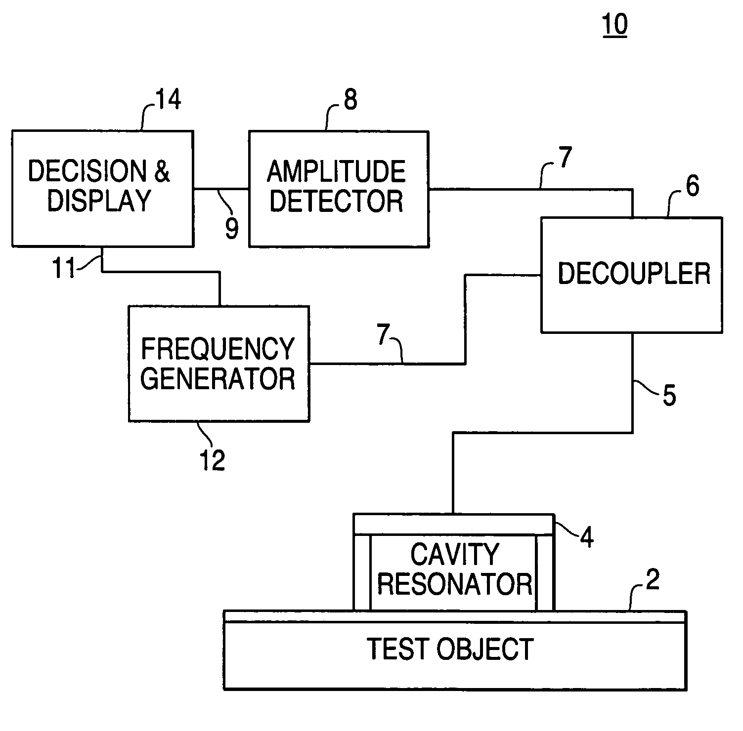
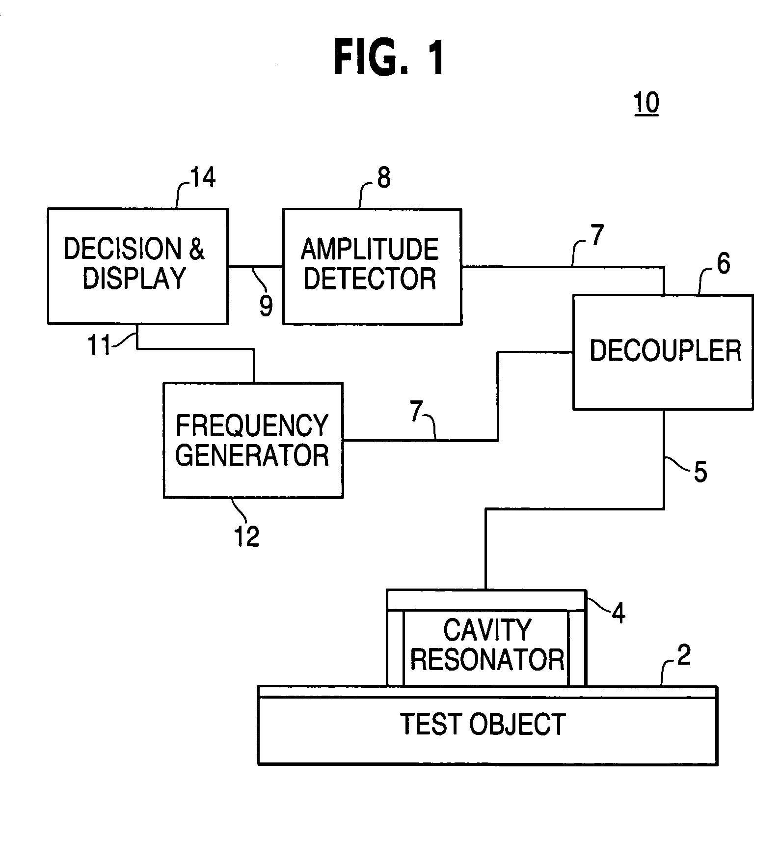
[0025]FIG. 1 is a block diagram of an exemplary measuring system 10. The exemplary measuring system 10 is shown with a test object 2 in proximity to an exemplary cavity resonator 4. The cavity resonator 4 has an exposed face and is connected via a line 5 to a decoupler 6. The decoupler 6, in turn, is connected to an amplitude meter 8 and a frequency generator 12 via lines 7. The amplitude meter 8 is connected to a decision and display unit 14 via line 9. The frequency generator 12 is also connected to the decision and display unit 14 via line 11.

[0026]In operation, the cavity resonator 4 is affixed to the sample or test object 2 with the exposed face abutting the test object 2. That is, the surface ...


PUM

PropertyMeasurementUnit
frequencyaaaaaaaaaa
thicknessaaaaaaaaaa
thicknessaaaaaaaaaa

Abstract

Film thickness measurement systems and methods are provided that utilize a signal generator having a Gunnplexer design and a resonant frequency detector to correlate the shift in resonant frequency experienced by a resonant cavity having one face abutting a test object. The shift is resonant frequency is determinative of a linear or near linear correlation between film thickness and the resonant frequency shift.

Description

FIELD OF THE INVENTION[0001]The present invention relates generally to the field of measurements. More particularly, the present invention relates to non-destructively measuring the thickness of a film using electromagnetic cavity resonance principles.BACKGROUND OF THE INVENTION[0002]Non-destructive measurement of a film thickness is an important objective for many industries. For example, in the aircraft industry paint for functional and decorative purposes is often applied to control surfaces which may have near critical weight. Also, prior to applying a surface paint, care must be taken to make sure that an adequate amount of primer is applied. To act as a proper corrosion inhibitor the primer must typically be applied uniformly to a desired thickness. For example, in some aircraft applications, a desired thickness is between 0.4 and 1.0 mils (thousandths of an inch) to the surface of the substrate. Moreover, depending on the model of aircraft over 500 pounds of primer paint may ...

Claims


Application Information

Patent Timeline
Patent Type & Authority Patents(United States)
IPC IPC(8): G01R27/04G01B15/02G01N22/00G01R27/26
CPCG01B15/02G01R27/2688G01N22/00
Inventor SERGOYAN, EDWARD G.CHAMPION, CORBINOLSEN, ROBERT G.
Owner THE BOEING CO
Why Eureka
Try Eureka