Tunable filter and portable telephone

a filter and portable technology, applied in the field of tunable filters, can solve the problems of low q, inability to obtain large variable inductance, and inability to achieve large dielectric losses of ferroelectric substances, and achieve excellent reliability and reproducibility, and small insertion loss

Inactive Publication Date: 2006-11-14
KK TOSHIBA
View PDF17 Cites 59 Cited by
  • Summary
  • Abstract
  • Description
  • Claims
  • Application Information

AI Technical Summary

Benefits of technology

[0012]The present invention provides a tunable filter which can change a pass band at wide frequency range, can continuously change the pass band, has small insertion loss, has precipitous shielding characteristic, can downsize, and has excellent reliability and reproducibility.

Problems solved by technology

However, filters having only remarkably limited performance can be achieved at present.
However, an attempt to obtain large variable inductance is not known, using an inductor element of high Q used in a high-frequency band of a few hundred MHz or above for portable telephones or the like.
However, a ferroelectric substance generally has large dielectric loss and has low Q.
However, this has a slow response and has a large size.
Therefore, the electromagnetic driving mechanism is not suitable for a mobile radio terminal such as a cellular phone.
While capacitance changes in the order of about two digits in on-off operations, capacitance disadvantageously changes continuously within a range of 1.5 times. Therefore, when the electrostatic driving type variable capacitor is applied to the tunable filter, it is difficult to realize the most demanded characteristic of continuously changing a band on a large scale, although a band can be digitally switched on a large scale.

Method used


Image

  • Tunable filter and portable telephone
  • Tunable filter and portable telephone
  • Tunable filter and portable telephone

Examples


first embodiment

(First Embodiment)

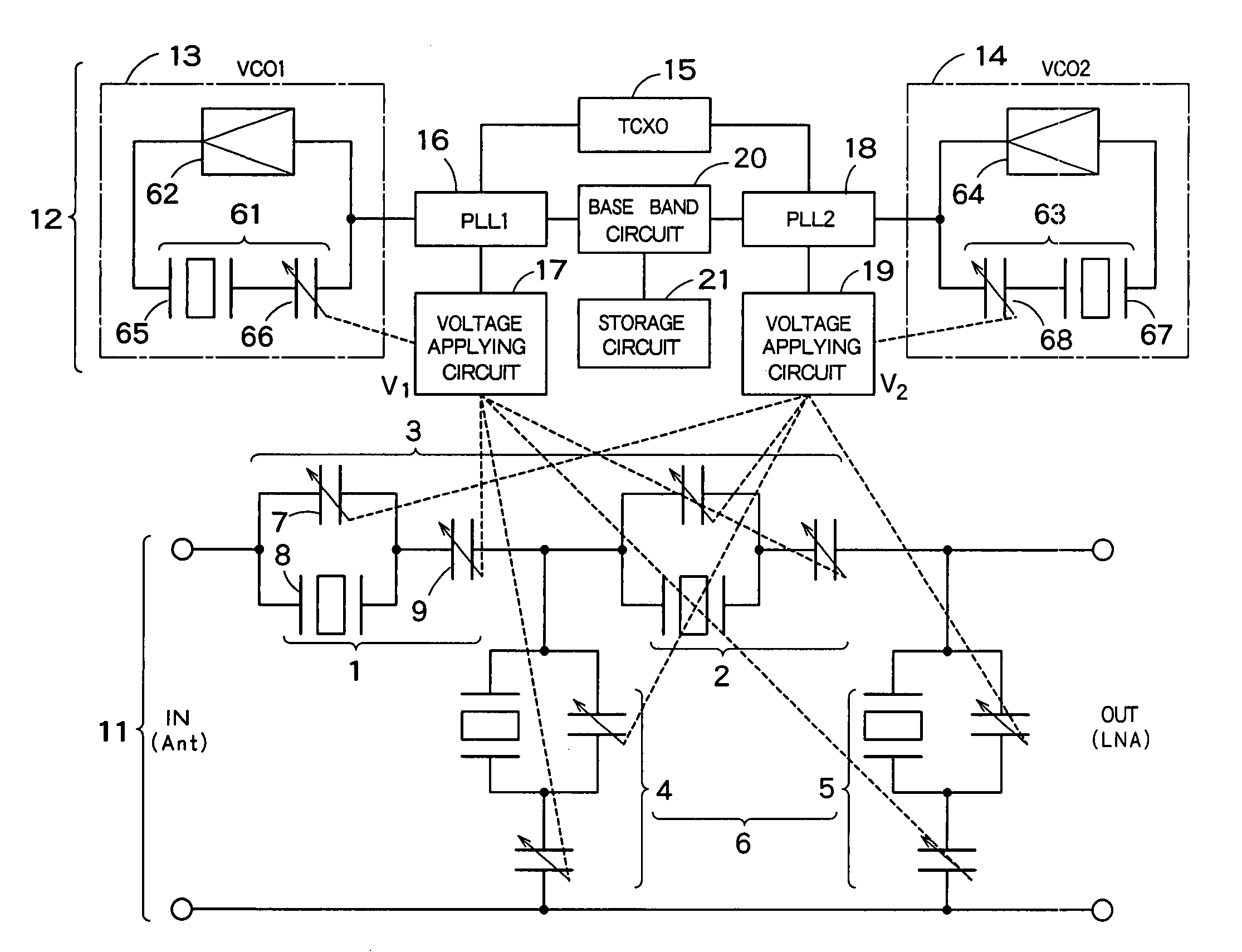
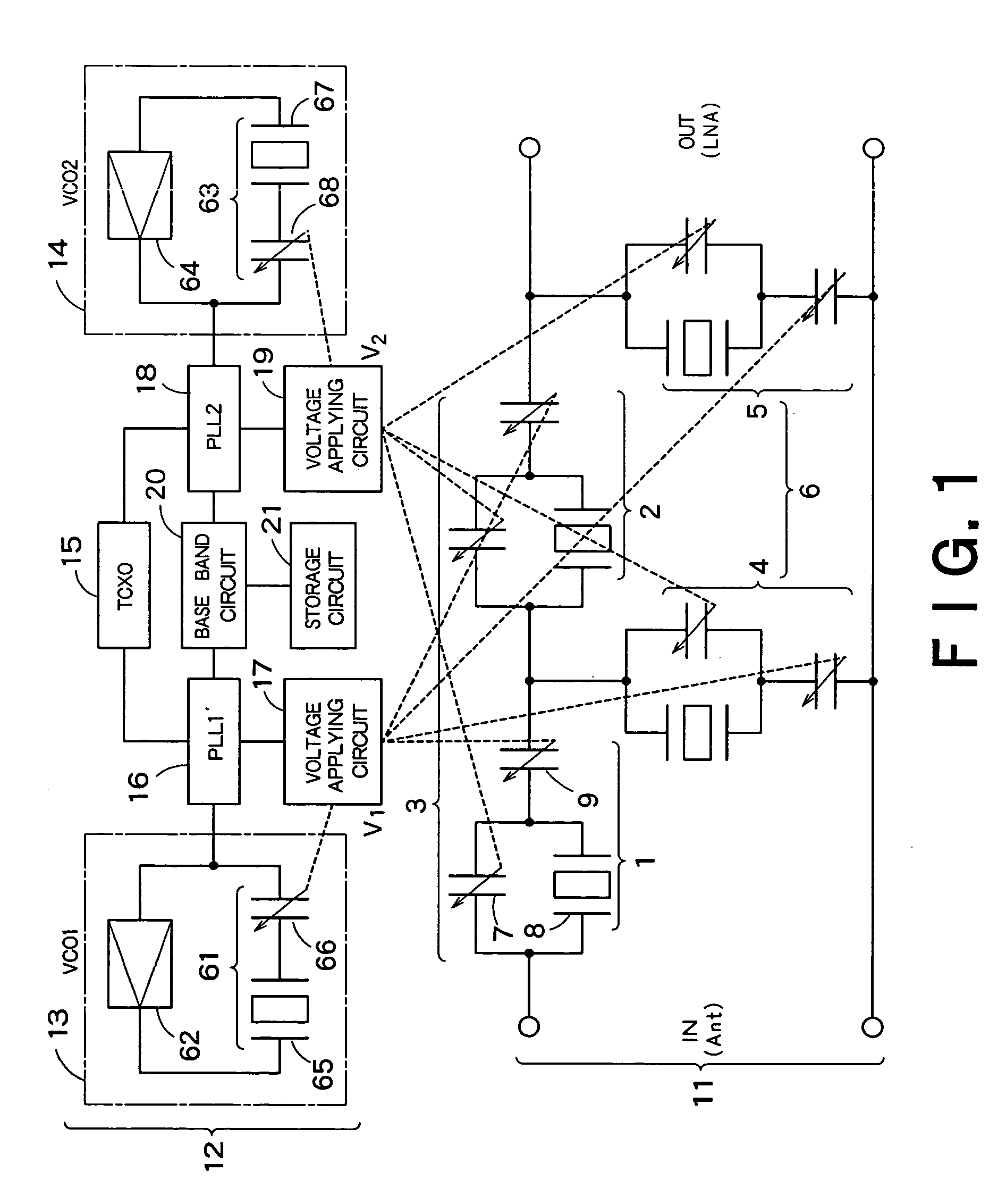
[0060]FIG. 1 is an equivalent circuit diagram of a tunable filter according to a first embodiment of the present invention. The tunable filter shown in FIG. 1 includes a filter main body 11, and a control circuit 12 that controls the filter main body 11.

[0061]The filter main body 11 is a ladder filter including a series resonance unit 3 having two resonance units 1 and 2 connected in series, and parallel resonance units 4 and 5 that are connected to between one end of the resonance units 1 and 2, respectively and an input / output common terminal. Each of the resonance units 1, 2, 4, and 5 has a variable capacitor 7 and a thin-film piezoelectric resonator, i.e., a film bulk acoustic resonator (FBAR) 8 that are connected in parallel, and a variable capacitor 9 that is connected in series with them. An upper electrode of the film bulk acoustic resonator 8 within the series resonance unit 3 and an upper electrode of the film bulk acoustic resonator 8 within the parallel...

second embodiment

(Second Embodiment)

[0084]A tunable filter according to a second embodiment is the same as that according to the first embodiment, except the circuit configuration of the filter main body 11 is different. Therefore, the difference is mainly explained hereinafter.

[0085]FIG. 10 is a circuit diagram of the filter main body 11 according to the second embodiment. The filter main body 11 shown in FIG. 10 includes two capacitors 71 and 72 that are connected in series, and a parallel resonance unit 75 having two resonance units 73 and 74 connected to between one end of the capacitors 71 and 72, respectively and an input / output common terminal. Each of the resonance units 73 and 74 has the film bulk acoustic resonator 8 and the variable capacitor 7 that are connected in parallel, and the variable capacitor 9 that is connected in series with them, like the resonator shown in FIG. 1. The number of resonators that constitute the parallel resonance unit 6 is not particularly limited to two.

[0086]...

third embodiment

(Third Embodiment)

[0089]A tunable filter according to a third embodiment is the same as that according to the first embodiment, except the circuit configuration of the filter main body 11 is different. Therefore, the difference is mainly explained.

[0090]FIG. 12 is a circuit diagram of the filter main body 11 according to the third embodiment. The filter main body 11 shown in FIG. 12 has a lattice filter configured by four resonators 76 connected in a bridge. Each resonance unit 76 has the film bulk acoustic resonator 8 and the variable capacitor 7 that are connected in parallel, and the variable capacitor 9 that is connected in series with them, like the resonator shown in FIG. 1.

[0091]Among the four resonators 76 shown in FIG. 12, the film bulk acoustic resonators 8 included in the two resonators on one diagonal line and the film bulk acoustic resonators 8 included in the two resonators on the other diagonal line have mutually different thicknesses in their upper electrodes 55. The...


PUM


Abstract

A tunable filter has a plurality of variable capacitors and a plurality of inductor elements, each being formed on a common substrate, a filter circuit formed by using at least a portion of the plurality of variable capacitors and a portion of the plurality of inductor elements, a monitor circuit formed by using at least a portion of the plurality of variable capacitors and a portion of the plurality of inductor elements, a detecting circuit which detects a prescribed circuit constant of the monitor circuit, a storage which stores information relating to a reference circuit constant of the monitor circuit, and a capacitance control circuit which controls capacitance of the variable capacitors in the monitor circuit and capacitance of the variable capacitors in the filter circuit, based on a result detected by the detecting circuit and information stored in the storage.

Description

CROSS REFERENCE TO RELATED APPLICATIONS[0001]This application claims benefit of priority under 35USC§119 to Japanese Patent Application No. 2004-23012, filed on Jan. 30, 2004, the entire contents of which are incorporated by reference herein.BACKGROUND OF THE INVENTION[0002]1. Field of the Invention[0003]The present invention relates to a tunable filter having a variable capacitor of which capacitance is variably controlled by a thin-film piezoelectric actuator and an inductor element.[0004]2. Related Art[0005]In the radio communication field, there is a strong demand for realizing a tunable filter that can continuously and freely change a pass band and a block band. Characteristics required for the tunable filter are, for example, a large band-change width, a continuous band change, small insertion loss and precipitous shielding characteristic as a filter (i.e., high Q), compactness and lightness, and high reliability and excellent reproducibility. However, filters having only rema...

Claims


Application Information

Patent Timeline
Patent Type & Authority Patents(United States)
IPC IPC(8): H03H21/00H03H9/54H03H9/64H01G7/06H03B5/00H03H7/075H03H7/12H03H9/00H03H9/17H03H9/46H03H9/58H03H9/60H03H11/04H03J1/00H03J3/08
CPCH03H9/542H03H9/605H03J1/0008H03J3/08H03H2210/012H03H2210/015
Inventor KAWAKUBO, TAKASHIOHARA, RYOICHIABE, KAZUHIDEYOSHIDA, HIROSHITSURUMI, HIROSHI
Owner KK TOSHIBA
Why Eureka
Try Eureka