Laser irradiation method and apparatus for forming a polycrystalline silicon film

a polycrystalline silicon and laser irradiation technology, applied in semiconductor/solid-state device testing/measurement, manufacturing tools, instruments, etc., can solve the problems of difficult evaluation and management of molten state, which should essentially be managed, and achieve superior reliability and reproducibility, the effect of improving the characteristics of products

Inactive Publication Date: 2009-01-06
VISTA PEAK VENTURES LLC
View PDF14 Cites 10 Cited by
  • Summary
  • Abstract
  • Description
  • Claims
  • Application Information

AI Technical Summary

Benefits of technology

[0018]According to the laser irradiation method and apparatus of the present invention, the threshold value of micro-crystallization is determined based on the reflected light of the flat-surface light from the first irradiated areas formed by the first pulse laser having the specific generation frequency. Based on the determined threshold value of micro-crystallization, an energy density is determined for the second pulse laser beam to be irradiated onto main irradiating process to form the second irradiated area. Therefore, on the second irradiated area, the surface of the substrate can be crystallized with superior reliability and reproducibility.
[0019]Also, when the threshold value of micro-crystallization is determined, the flat-surface light is incident in the direction substantially parallel to the major axis of the elongate pulse laser beam to receive the reflected light from the first irradiated areas. Since changes in the micro-crystallized structure which appear periodically in the minor-axis direction of the beam are detected with higher accuracy by analyzing the reflected light, the micro-crystallization threshold value can be determined extremely accurately.
[0024]According to the laser irradiation technique and apparatus of the present invention, the threshold value of micro-crystallization is determined based on the reflected light of the flat-surface light reflected from the first irradiated areas. An energy density is determined based on the threshold value of micro-crystallization for the main irradiation for irradiating the laser beam onto the second irradiated area, to suitably crystallize the second irradiated area. As a result, the surface of a substrate can be crystallized with superior reliability and reproducibility. By thus crystallizing the surface of a substrate with superior reliability and reproducibility, characteristics of products can be improved and the manufacturing yield of products can be increased. In addition, by automatically determining the threshold value of micro-crystallization, the manufacturing throughput of products can be increased.
[0025]According to the laser irradiation technique and apparatus of the present invention, the estimation light is incident in the direction substantially parallel to the major axis of the scanning pulse laser beam, to receive and analyze the reflected light of the estimation light from the first irradiated areas. This allows detection of the micro-crystallized structure with a higher accuracy, as a result of which the threshold value of micro-crystallization can be exactly determined. By setting the scanning pitch of the scanning in the first irradiated areas to be larger than that to be used in the main irradiation in the laser irradiation technique and apparatus of the present invention, the throughput in scanning irradiation on the first irradiated areas can be improved. Alternatively, by using the first pulse laser beam having a size smaller than the size of the second pulse laser beam, the first irradiated areas can be made smaller to increase the area for the main irradiation. Accordingly, the yields of products can be improved.

Problems solved by technology

This is because the molten state which should essentially be managed is difficult to evaluate and manage.

Method used


Image

  • Laser irradiation method and apparatus for forming a polycrystalline silicon film
  • Laser irradiation method and apparatus for forming a polycrystalline silicon film
  • Laser irradiation method and apparatus for forming a polycrystalline silicon film

Examples


second embodiment

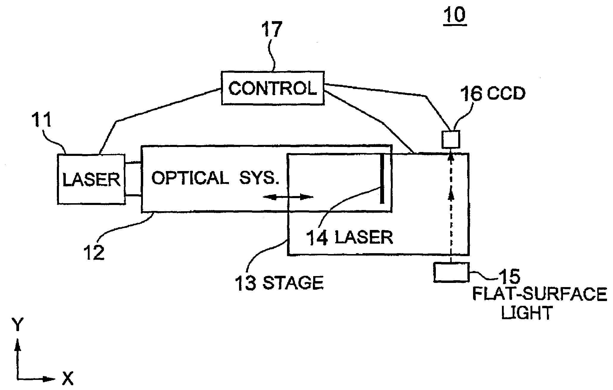
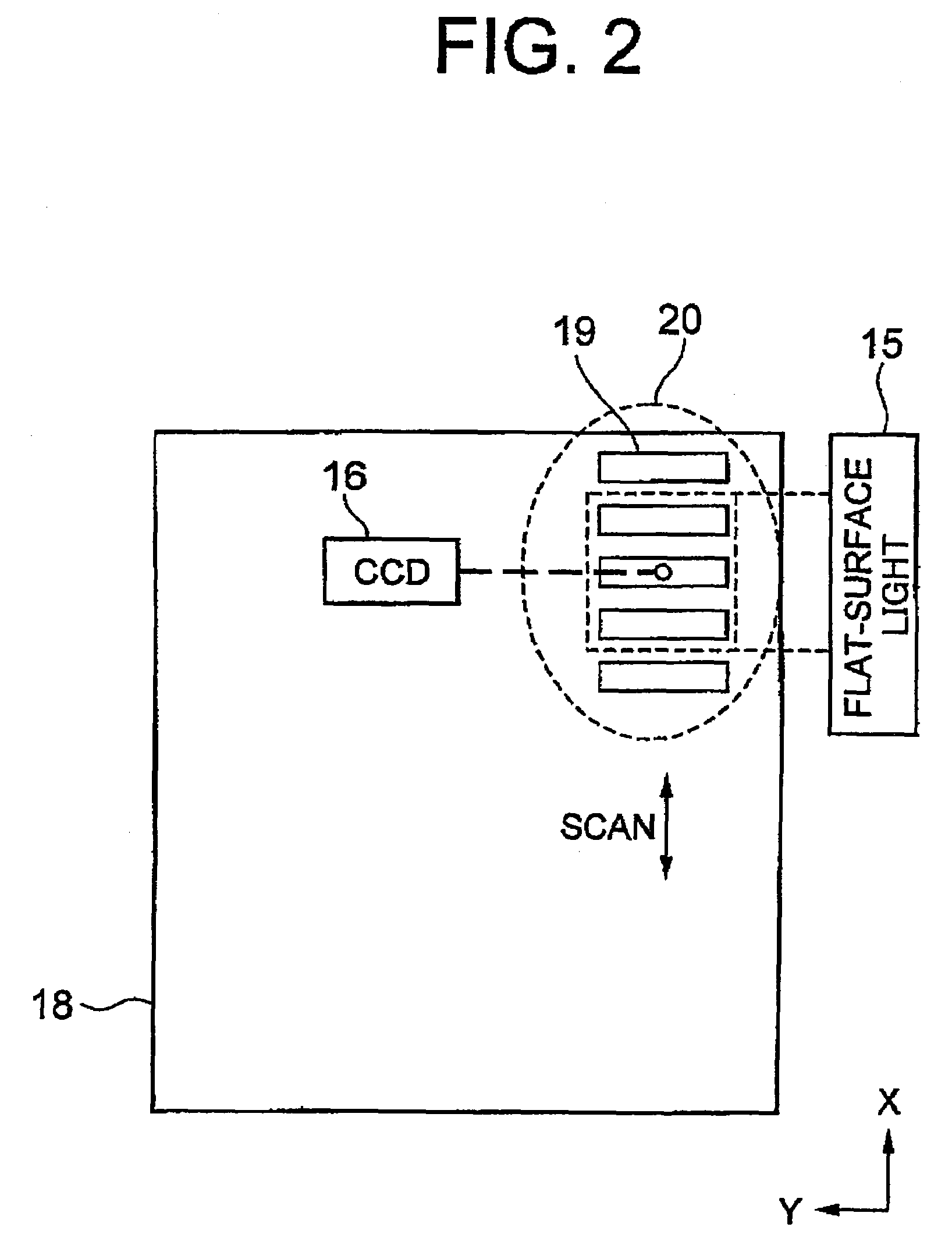
[0059]A laser irradiation apparatus according to the present invention has a structure to similar that of the laser irradiation apparatus of the first embodiment, except that the optical resolution of the CCD light-sensitive element 16 in the second embodiment is coarser than the width of the portion of the coarse crystal grains in the scanning direction. The optical resolution of the CCD light-sensitive element 16, which is coarser than the width of the portion of the coarse crystal grains in the scanning direction, does not allow the color changes between the micro-crystallized portions and portions of the coarse crystal grains to be distinguished clearly based on the image obtained by receiving the reflected light from the irradiated area. That is, substantially only colors of the micro-crystallized portions are detected.

[0060]FIG. 7 shows changes in luminance of the reference color of the light received by the CCD light-sensitive element 16. For achieving the state shown by grap...


PUM

PropertyMeasurementUnit
grain diameteraaaaaaaaaa
sizeaaaaaaaaaa
sizeaaaaaaaaaa

Abstract

A method for changing an amorphous silicon film to a poly-crystalline silicon film includes the steps of irradiating an elongate pulse laser beam onto the silicon film while scanning in the direction normal to the major axis of the elongate pulse laser beam, to form a plurality of irradiated areas, irradiating flat-surface light onto the irradiated areas in the direction parallel to the major axis, and analyzing distribution of the reflected light from the irradiated areas to determine the threshold value of micro-crystallization. The threshold value is used to further determine an energy density of the elongate pulse laser beam for the phase change process.

Description

TECHNICAL FIELD[0001]The present invention relates to a laser irradiation method and a laser irradiation apparatus, and more specifically, to a laser irradiation method adopted in a laser annealing process to form a polycrystalline silicon (poly-Si) thin film by irradiating a laser beam onto a silicon film, and a laser irradiation apparatus adopting such a laser irradiation method.BACKGROUND ART[0002]In recent years, as a thin-film device to form an integrated circuit on a glass substrate, poly-Si TFTs (thin film transistors) have been vigorously developed. The poly-Si film is generally formed in an excimer laser crystallization technique. In this technique, an amorphous silicon (a-Si) film is once formed, and an excimer laser beam is irradiated onto the a-Si film to melt and re-crystallize the a-Si film, to form the poly-Si film. In the excimer laser crystallization technique, the molten state of the a-Si film depends on the film thickness thereof, optical constant of the film, wav...

Claims


Application Information

Patent Timeline
Patent Type & Authority Patents(United States)
IPC IPC(8): H01L21/263
CPCH01L21/02678H01L21/02691H01L22/12H01L27/1285B60B21/10B60C17/066
Inventor OKUMURA, HIROSHI
Owner VISTA PEAK VENTURES LLC
Why Eureka
Try Eureka