Variable nozzle control apparatus of turbocharger
a control apparatus and variable nozzle technology, applied in the direction of electric control, machines/engines, combustion engines, etc., can solve the problems of complex design of duty solenoid valves, inability to exhibit resolution, and inability to control nozzles properly, so as to reduce load
- Summary
- Abstract
- Description
- Claims
- Application Information
AI Technical Summary
Benefits of technology
Problems solved by technology
Method used
Image
Examples
first embodiment
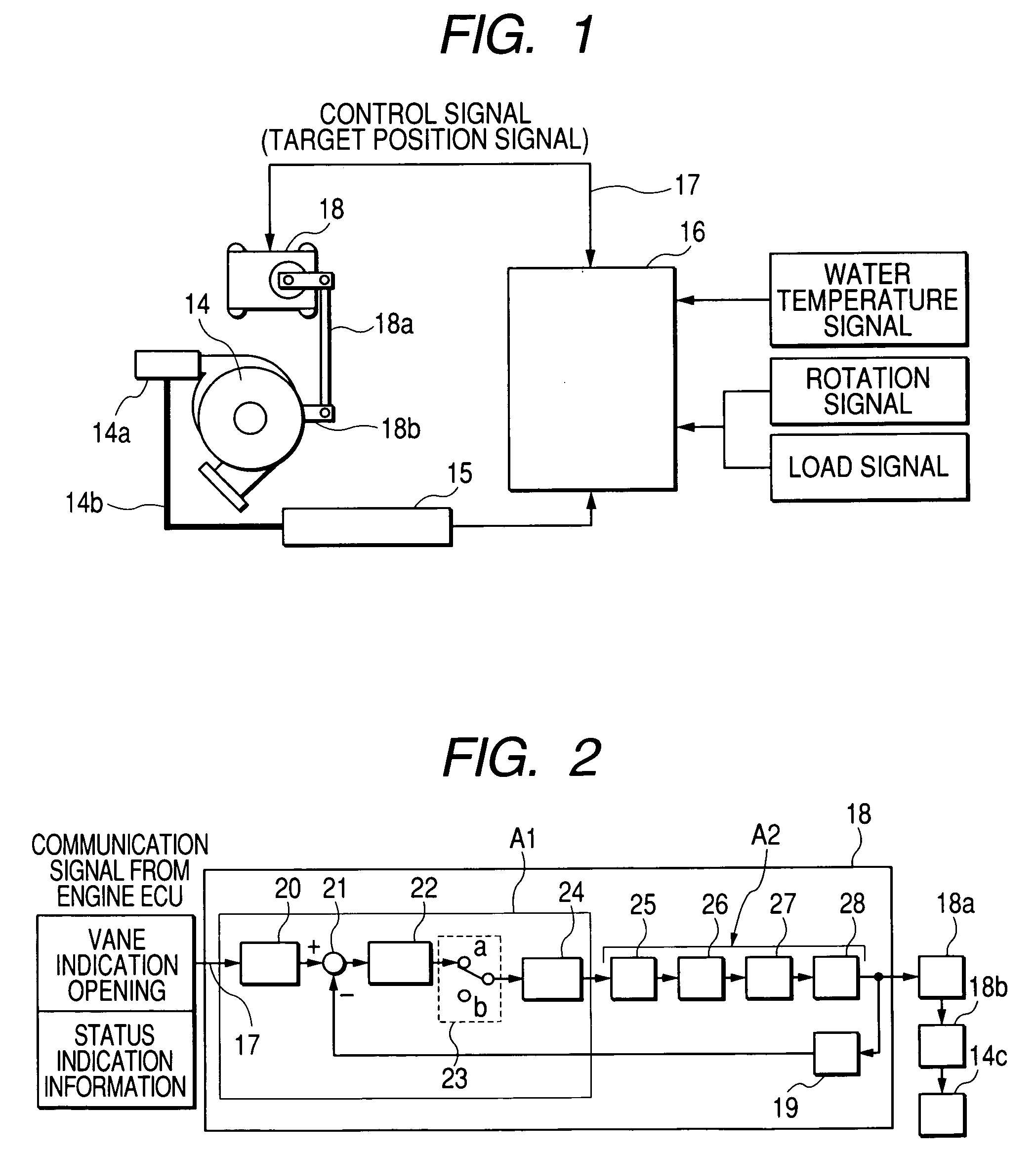
[0047]Next, the first embodiment of the variable nozzle control apparatus of the turbocharger according to the invention and an operation thereof will be described with reference to FIGS. 2 and 3.
[0048]FIG. 2 is a block diagram showing the variable nozzle control apparatus of the turbocharger according to the first embodiment of the invention. Description will be given to the first embodiment.
[0049]The electronic control actuator 18 comprises an electronic control circuit section A1 and a driving section A2. The actual angle signal of an output shaft is fed back from the output side of the driving section A2 to the comparing device of the electronic control circuit section A1 through an angle sensor 19. In the electronic control circuit section A1, an angle signal converting device 20, a comparing device 21, a calculating device 22 constituted by a PID calculating section, a change-over switch 23 and a motor driving logic generating device 24 are sequentially connected, various comm...
second embodiment
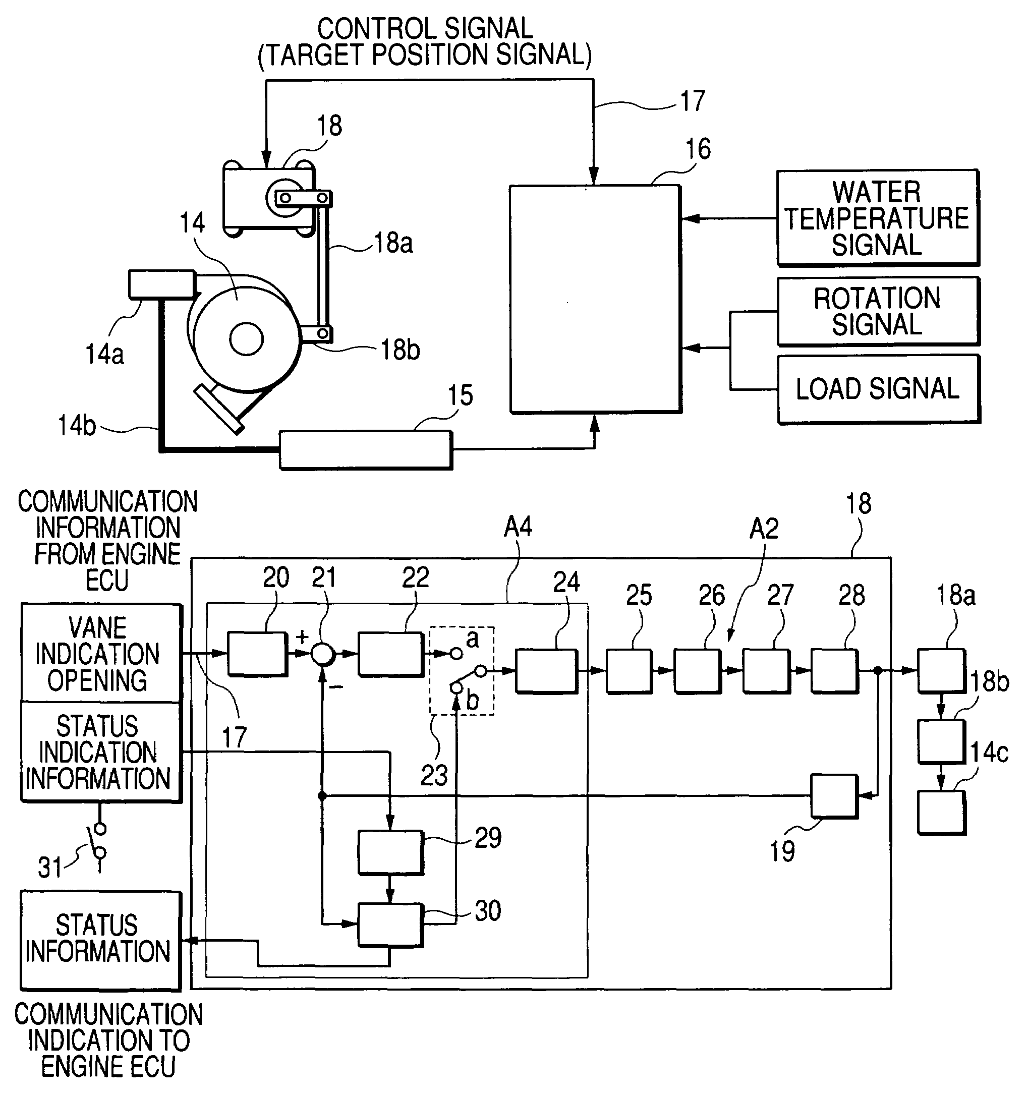
[0054]FIG. 3 is a block diagram showing the variable nozzle control apparatus of the turbocharger according to the second embodiment of the invention. Description will be given to the second embodiment. FIG. 3 is a diagram showing a structure in which a function of causing the vane 14c of the variable nozzle to carry out a wiping operation is added to the structure of the block circuit in FIG. 2.
[0055]The electronic control actuator 18 comprises an electronic control circuit section A4 and the driving section A2. The driving section A2 and the other structures are the same as those in the first embodiment and description thereof will be omitted. Moreover, the structure of the electronic control circuit section A4 is the same as that of the electronic control circuit section A1 except that wiping command device and wiping processing device which will be described below are added. The electronic control circuit section A4 includes a wiping command device 29 and a wiping processing dev...
third embodiment
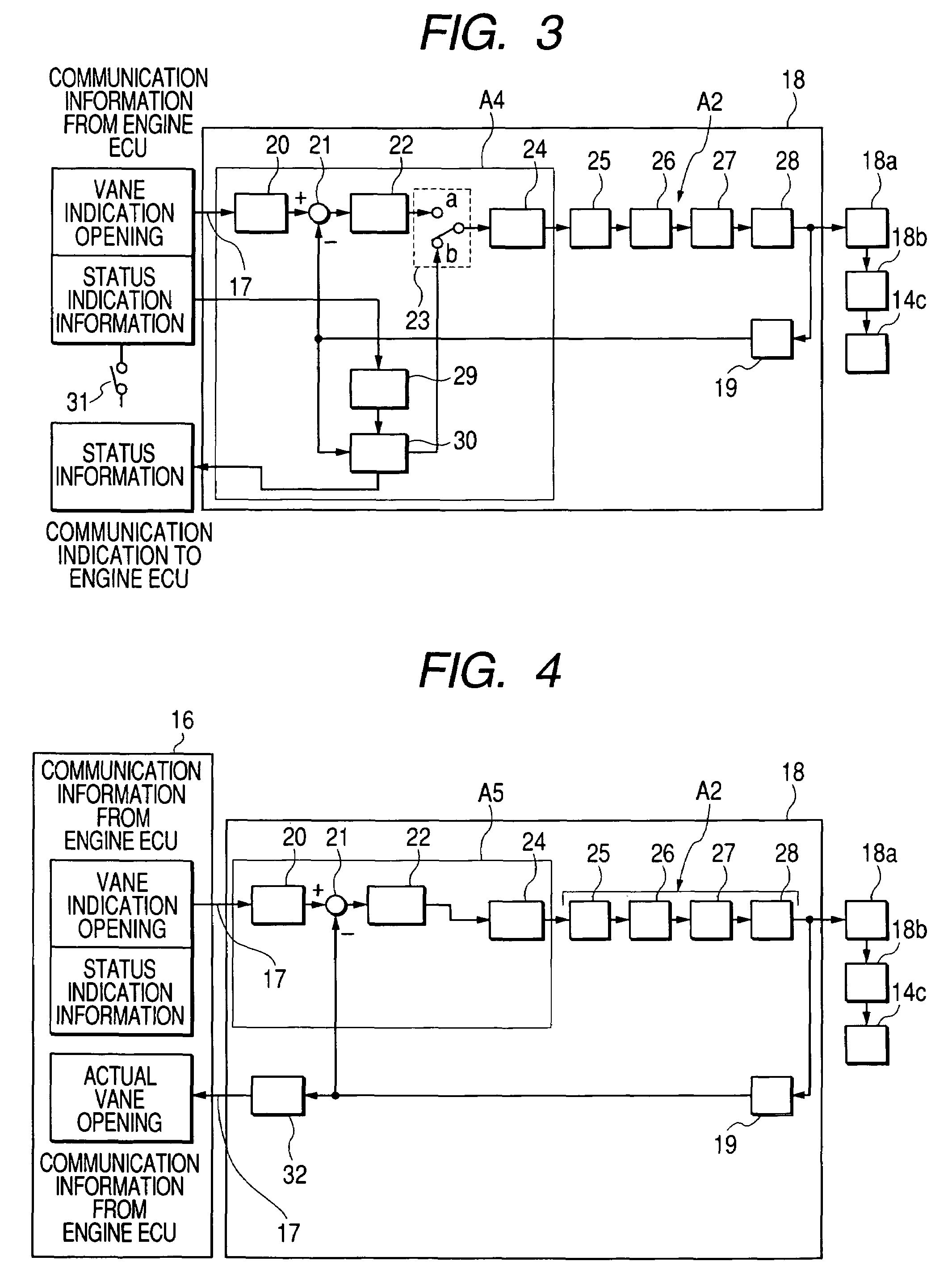
[0059]FIG. 4 shows is a block diagram showing the third embodiment of the variable nozzle control apparatus of the turbocharger according to the invention. Description will be given to the third embodiment.
[0060]The electronic control actuator 18 includes an electronic control circuit section A6 and a driving section A2 that is controlled and driven by the electronic control circuit section A5. The electronic control circuit section A5 includes an angle signal converting device 20 for introducing an indication signal for the opening of the vane of the variable nozzle through a control signal line 17, a comparing device 21 for comparing a target angle signal of the output shaft with an actual angle signal of the output shaft, a calculating device 22 constituted by a PID calculating section for carrying out integration, differentiation and proportional control to the output signal from the comparing device 21, a motor driving logic generating device 24 connected to an output side of t...
PUM
 Abstract
Description
Claims
Application Information
 - R&D
- Intellectual Property
- Life Sciences
- Materials
- Tech Scout
- Unparalleled Data Quality
- Higher Quality Content
- 60% Fewer Hallucinations
Browse by: Latest US Patents, China's latest patents, Technical Efficacy Thesaurus, Application Domain, Technology Topic, Popular Technical Reports.
© 2025 PatSnap. All rights reserved.Legal|Privacy policy|Modern Slavery Act Transparency Statement|Sitemap|About US| Contact US: help@patsnap.com


