Vapor chamber

a technology of vapor chamber and liquid phase working fluid, which is applied in the field of heat pipes, can solve the problems of small flow cross-sectional area of flow path, inability to meet the needs of cooling, so as to achieve the effect of improving heat transporting characteristics and increasing capillary pressur

Active Publication Date: 2006-11-21
THE FUJIKURA CABLE WORKS LTD +1
View PDF15 Cites 28 Cited by
  • Summary
  • Abstract
  • Description
  • Claims
  • Application Information

AI Technical Summary

Benefits of technology

[0010]An object of the present invention is the further improvement of the heat transport capacity of a vapor chamber by promoting a reflux of a liquid phase working fluid to an evaporating part.
[0013]According to the present invention, therefore, greater capillary pressure is created in the first wick, in comparison with that created in the second wick, and the flow resistance in the second wick smaller than that in the first wick. Accordingly, the working fluid is evaporated by the heat input into the evaporating part from the external environment. The capillary pressure at a meniscus of the fluid formed on a surface of the first wick is high(i.e., a pumping force is great), and the flow resistance in the second wick in the condensing part is small. Therefore, the liquid phase working fluid refluxes to the evaporating part promptly and efficiently. As a result, there is a smooth circulation of the fluid in the vapor chamber, so that the heat transporting characteristics are be improved.

Problems solved by technology

At the same time, the cooling of a personal computer, a server, or a portable electronics device, which are enhanced in compactness and capacity, has been becoming a problem in recent days.
However, a flow path is formed by the cavity created among the fine powders as the material of a porous body, so that the flow cross-sectional area of the flow path has to be small and as intricate as a maze.
However, on the other hand, there is a disadvantage because the flow resistance against the liquid phase working fluid is relatively high.
For this reason, if the input amount of heat from outside increases suddenly and drastically, for example, the wick may dry out due to a shortage of the liquid phase working fluid to be fed to the portion where the evaporation of the working fluid takes place.

Method used


Image

  • Vapor chamber
  • Vapor chamber
  • Vapor chamber

Examples


Embodiment Construction

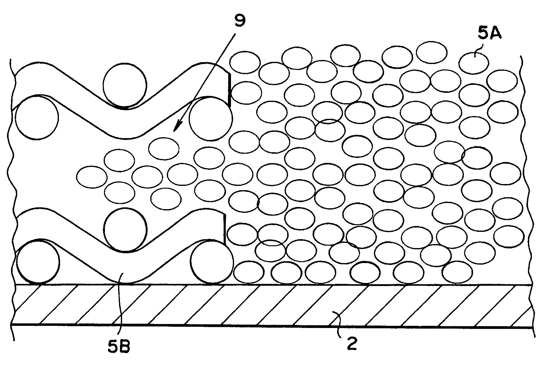
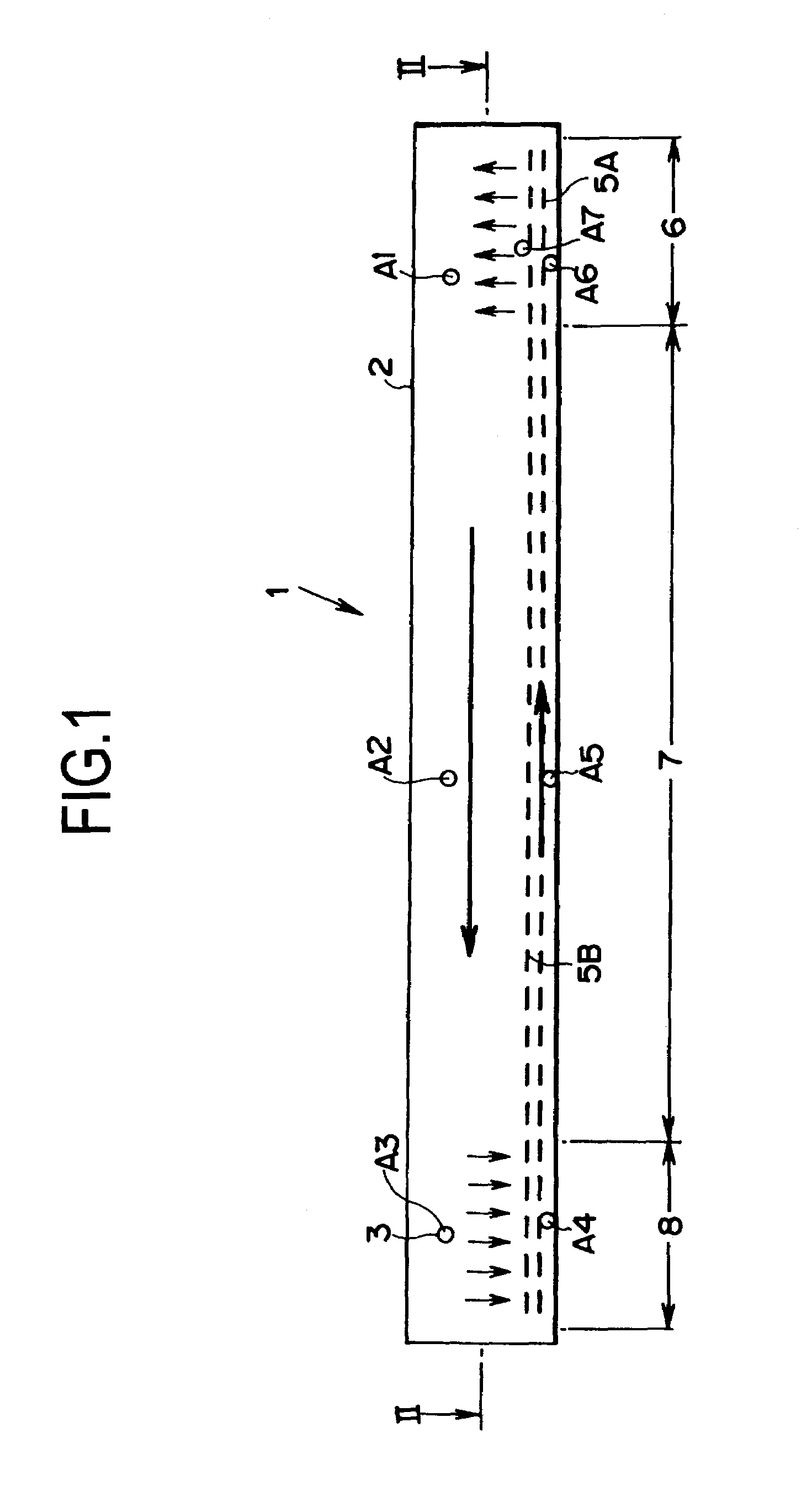
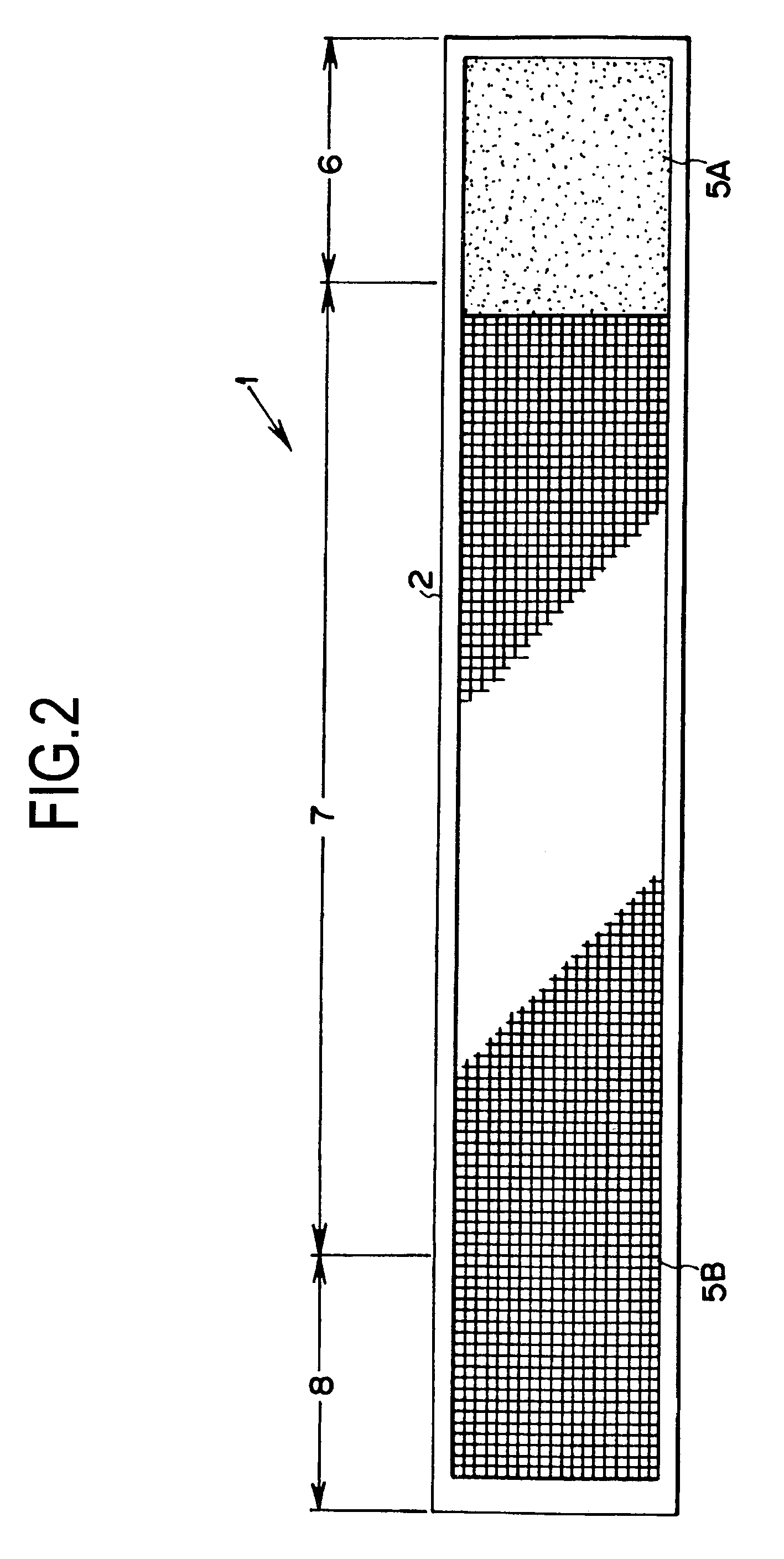
[0021]Here will be described an exemplary embodiment of the present invention. FIG. 1 is a schematic view showing one specific example of a vapor chamber according to the present invention, and FIG. 2 is a cross-sectional perspective view from line 11—11 of FIG. 1. This vapor chamber 1 has a structure comprising at least two wicks, wherein a wick 5A having a large capillary pressure is arranged in an evaporating part 6, and wherein a wick 5B, having a small flow resistance against the working fluid, is arranged in a heat insulating part 7 and in a condensing part 8. In the vapor chamber 1, moreover, a condensable fluid such as water is encapsulated as a working fluid 3 in a container (i.e., a hollow sealed container) 2 sealed in an air-tight condition, from which a non-condensable gas such as air is evacuated.

[0022]Specifically, the container 2 is made of a metal, such as copper, having high heat conductivity, and is formed into a thin cuboid. Hence the upper and lower faces of the ...


PUM


Abstract

A vapor chamber, in which a condensable fluid, which evaporates and condenses depending on a state of input and radiation of a heat, is encapsulated in a hollow and flat sealed receptacle as a liquid phase working fluid; and in which the wick for creating the capillary pressure by moistening by the working fluid is arranged in said sealed receptacle, comprising: a wick for creating a great capillary pressure by being moistened by said working fluid, which is arranged on the evaporating part side where the heat is input from outside; and a wick having a small flow resistance against the moistening working fluid, which is arranged on the condensing part side where the heat is radiated to outside.

Description

[0001]The present invention claims the benefit of Japanese Patent Application No. 2003-425494, filed on Dec. 22, 2003 in the Japanese Patent Office, the disclosure of which is incorporated herein by reference in its entirety.BACKGROUND OF THE INVENTION[0002]1. Field of the Invention[0003]The present invention relates to a heat pipe for transporting heat as latent heat of a working fluid or a condensable fluid, and relates especially to a vapor chamber in which a sealed receptacle is shaped into a tabular shape, i.e., a flat rectangular plate, and which is constructed to create a pumping force for refluxing a liquid phase working fluid to a portion where it evaporates, by means of a capillary pressure.[0004]2. Discussion of the Related Art[0005]In the customary way, a heat pipe for transporting heat in the form of latent heat of a working fluid is well known in the prior art. The heat pipe of this kind is a heat conducting element encapsulating a condensable fluid such as water in a ...

Claims


Application Information

Patent Timeline
Patent Type & Authority Patents(United States)
IPC IPC(8): F28D15/00F28D15/02F28D15/04
CPCF28D15/0233F28D15/046
Inventor KAWAHARA, YOUJITAKADA, NORIYUKIMOCHIZUKI, MASATAKAMASHIKO, KOICHISAITO, YUJIKOBAYASHI, TETSUYATAKAMIYA, AKIHIROSANO, TADASHIKIYOOKA, FUMITOSHIAGATA, HIROAKI
Owner THE FUJIKURA CABLE WORKS LTD
Why Eureka
Try Eureka