Pipe joint structure and method of assembling same

a pipe joint and pipe joint technology, applied in the direction of hose connections, liquid fuel feeders, machines/engines, etc., can solve the problems of high welding accuracy, high manufacturing cost, and inability to bond with laser welding,

Active Publication Date: 2006-11-21
DENSO CORP
View PDF18 Cites 9 Cited by
  • Summary
  • Abstract
  • Description
  • Claims
  • Application Information

AI Technical Summary

Benefits of technology

[0010]An object of the present invention is to provide a pipe joint structure in which a distribution pipe is fluid tightly joined to a vessel for accu

Problems solved by technology

To satisfy this requirement, dimensions of parts constituting the common rail body J1 and the screw threaded joint fitting J8 have to be highly accurate and it is necessary to use expensive welding technology such as laser welding technology, which results in higher manufacturing cost.
However, though the middle or high carbon steel can be bonded by resistance welding which is not expensive, they

Method used


Image

  • Pipe joint structure and method of assembling same
  • Pipe joint structure and method of assembling same
  • Pipe joint structure and method of assembling same

Examples


first embodiment

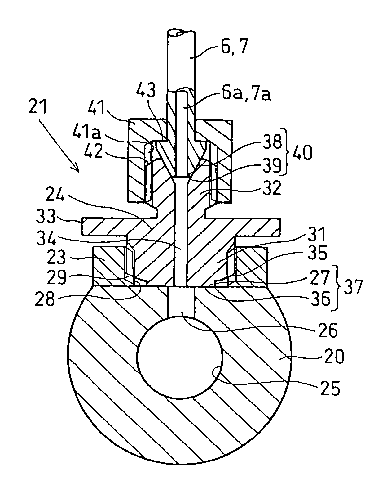
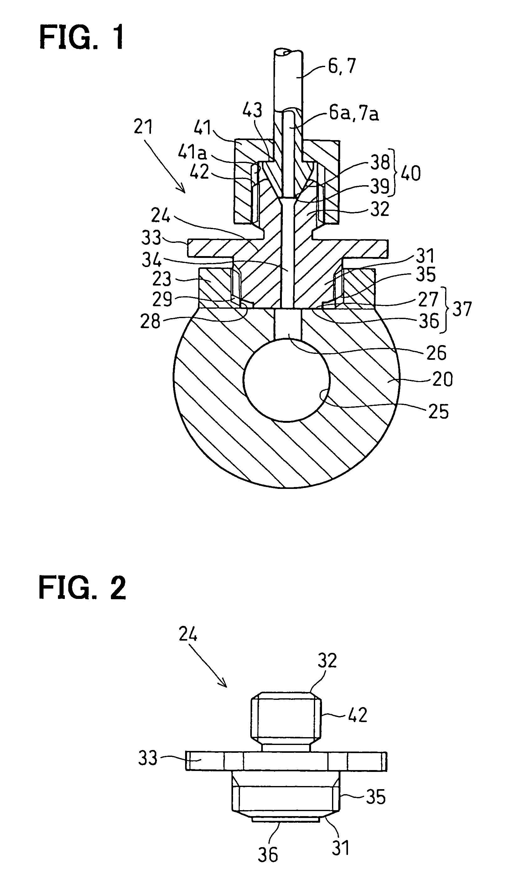
[0047]the present invention is described with reference to FIG. 1 to 3.

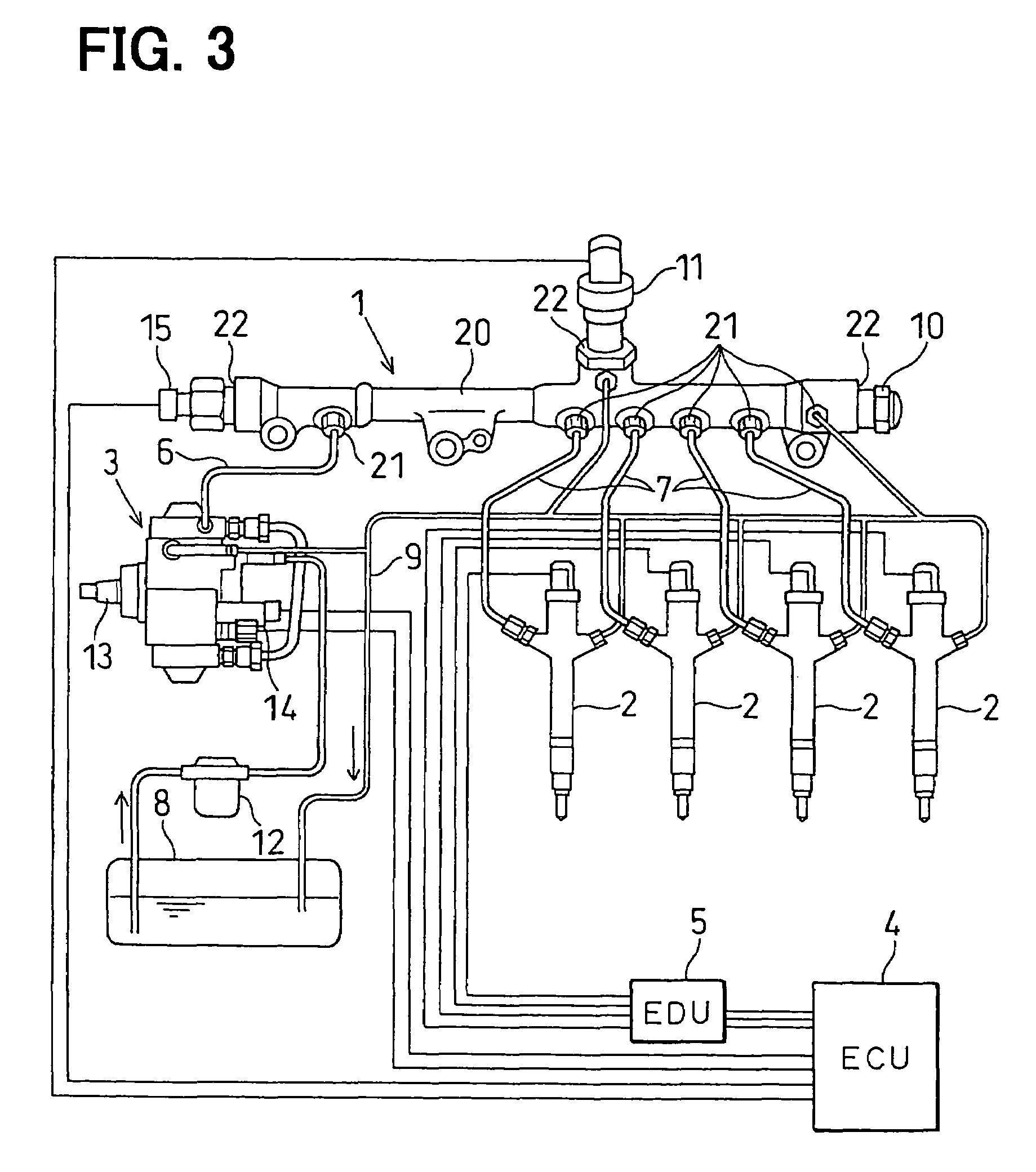
[0048]As shown in FIG. 3, a common rail type fuel injection system, for example, a system of injecting fuel to a four cylinder engine such as a diesel engine (not shown), is composed of a common rail 1, injectors 2, a supply pump 3, ECU 4 (Engine Control Unit), EDU 5 (Engine Driving Unit) and so on.

[0049]The common rail 1 is a pressure accumulation vessel in which high pressure fuel to be supplied to the injectors 2 is accumulated. The common rail 1 is connected via a high pressure pump distribution pipe 6 to a discharge port of the supply pump for feeding high pressure fuel thereto through the high pressure pump distribution pipe 6 so that common rail pressure corresponding to a fuel injection pressure is accumulated therein. A plurality of injector distribution pipes 7 are joined to the common rail 1 for supplying high pressure fuel to the respective injectors 2. Details of a pipe joint structure in which the h...


PUM


Abstract

In a pipe joint structure, a second screw thread formed on an outer circumference end of a joint member is screwed deep into a first screw thread formed on an inner circumference of a cylindrical joint fitting member whose axial end is bonded to a common rail body so that a second flat surface at an axial end of the joint member is pressed against a first flat surface on an outer circumference of the common rail body to form a fluid tight sealing surface therebetween in a state that a fluid passage opened to the second flat surface communicates with a through-hole opened to the first flat surface. Accordingly, even if a position of the joint fitting member to the common rail body is slightly shifted, fluid tight sealing between the first and second flat surfaces is assured.

Description

CROSS REFERENCE TO RELATED APPLICATIONS[0001]This application is based upon and claims the benefit of priority of Japanese Patent Applications No. 2003-103129 filed on Apr. 7, 2003, No. 2003-151217 filed on May 28, 2003 and No., 2004-54842 filed on Feb. 27, 2004, the contents of which are incorporated herein by reference.BACKGROUND OF THE INVENTION[0002]1. Field of the Invention[0003]The present invention relates to a pipe joint structure or a method of assembling main parts of the pipe joint structure in which a distribution pipe is joined to a vessel for accumulating fluid, in particular, applicable to a pipe joint structure including a vessel for accumulating high pressure fluid such as a common rail body in a common rail type fuel injection system.[0004]2. Description of Related Art[0005]It is known that a pipe joint structure in which a distribution pipe (such as a distribution pipe for a high pressure pump or a distribution pipe for an injector) is joined to a common rail body...

Claims


Application Information

Patent Timeline
IPC IPC(8): F16L41/00F02M69/46F16L5/00F02M55/00F02M55/02F16L41/03F16L41/08
CPCF02M55/005F02M55/025F16L41/086F16L41/14
Inventor KONDO, JUNNISHIWAKI, TADASHI
Owner DENSO CORP
Why Eureka
Try Eureka