Electric power distribution unit for electric connection box and electric connection box

a technology of electric connection box and electric connection box, which is applied in the direction of air-break switch, electrical apparatus construction details, transportation and packaging, etc., can solve the problems of large space occupied by electric connection box, complex structure of bus bar board itself, and increase in space occupied by bus bar board

Inactive Publication Date: 2006-11-21
AUTONETWORKS TECH LTD +2
View PDF7 Cites 9 Cited by
  • Summary
  • Abstract
  • Description
  • Claims
  • Application Information

AI Technical Summary

Benefits of technology

[0024]Further, the bus bar board is provided along an outer wall of the case, the outer wall is provided with electrical component-fitting portions for receiving electrical components, such as fuse elements, and a board connector mounted on at least one of the control circuit board and the relay board is oriented in a direction opposite to the electrical component-receiving portion. Accordingly, it is possible to incorporate the electric power distribution unit in the case of the electric connection box in a compact manner without interference between the electrical component-fitting portion and the relay board connector.

Problems solved by technology

If such a relay switch is incorporated in the bus bar board in the same conventional manner, the space occupied by the bus bar board will increase, and thus the electric connection box will become large in size.
Consequently, the structure of the bus bar board itself will be complicated.

Method used


Image

  • Electric power distribution unit for electric connection box and electric connection box
  • Electric power distribution unit for electric connection box and electric connection box
  • Electric power distribution unit for electric connection box and electric connection box

Examples


Embodiment Construction

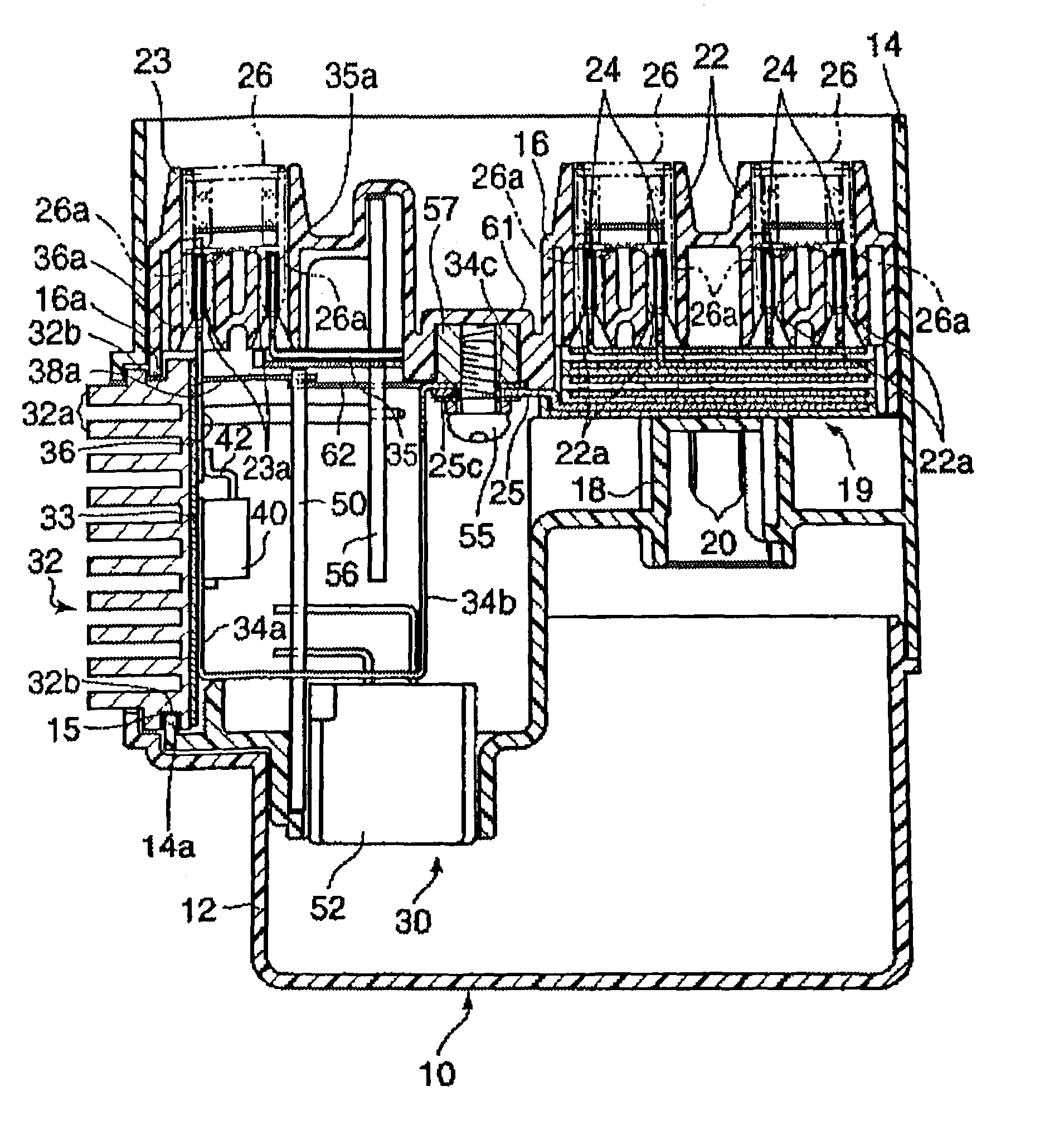
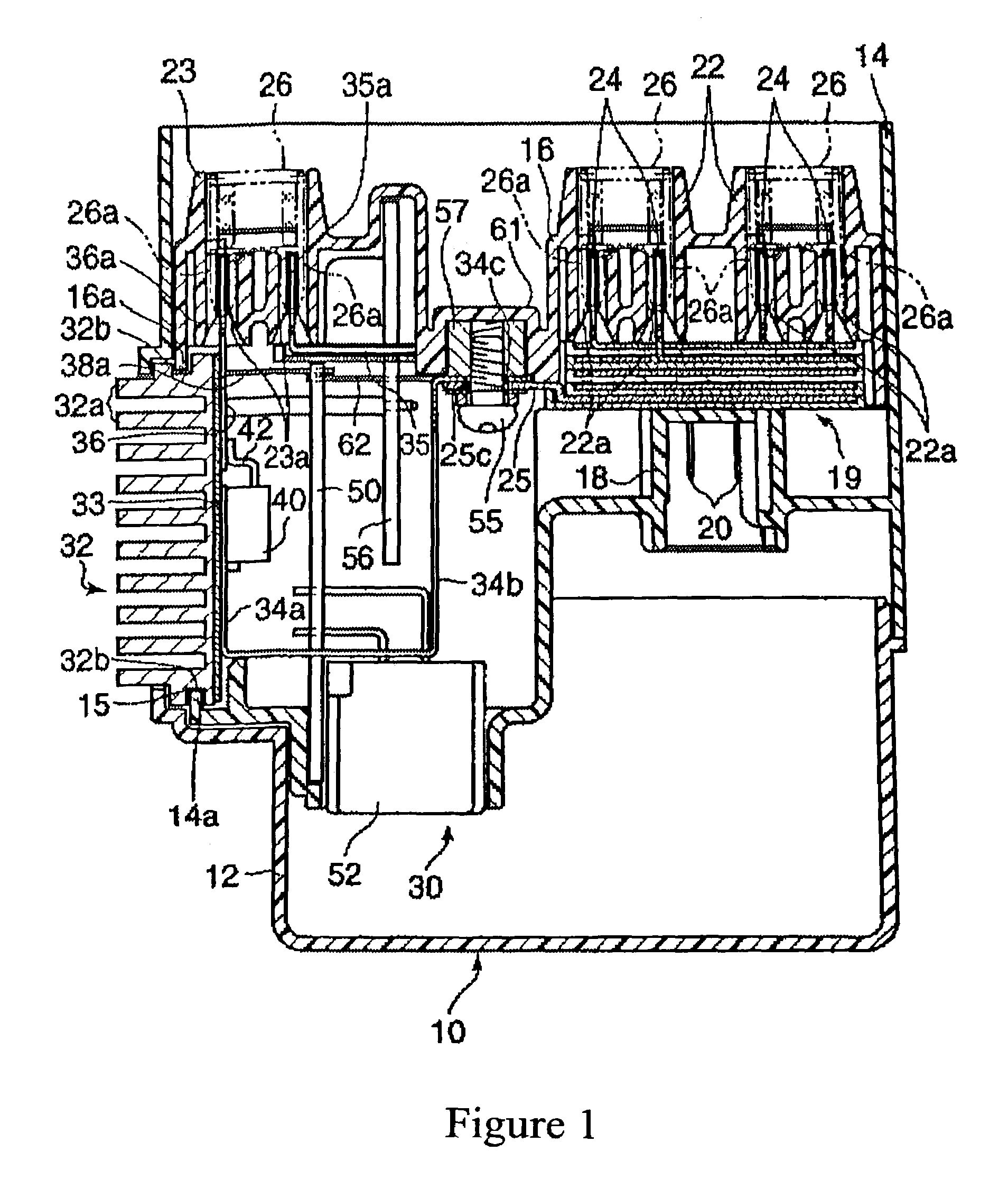
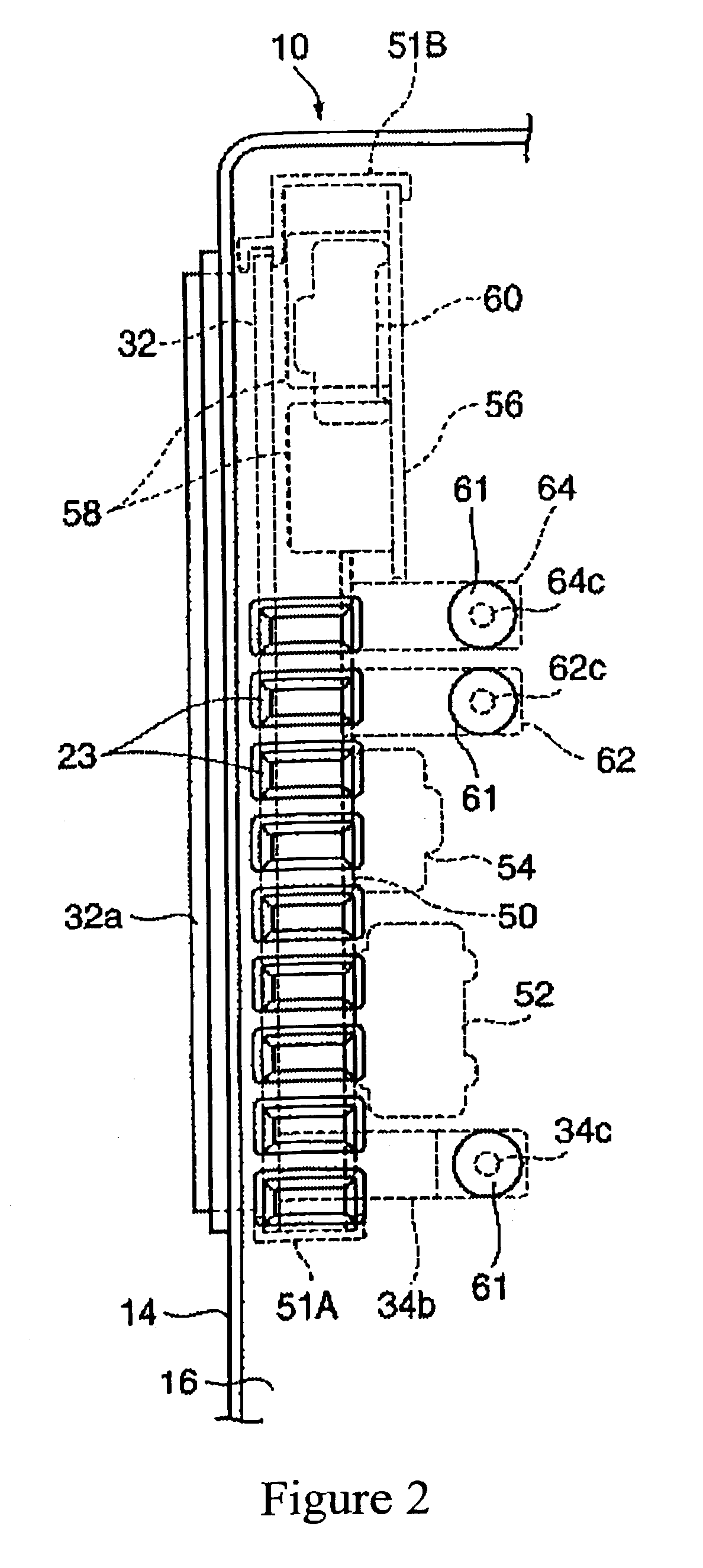
[0030]Referring now to the drawings, an exemplary embodiment of an electric connection box in accordance with the present invention will be described below.

[0031]An electric connection box shown in FIGS. 1 to 3 includes a lower case 12, an upper case 14 stacked on the lower case 12, and a case cover 16 mounted on the upper case 14. The upper and lower cases 14 and 12 and case cover 16 may be made of an insulating material, such as a synthetic resin material or the like, to form a case (insulating case) of the present invention.

[0032]Each of the upper and lower cases 14 and 12 may be formed in the shape of an open container with a bottom wall. An upper side of the lower case 12 covers a bottom wall of the upper case 14.

[0033]A bus bar board 19 is contained in the upper case 14. The bus bar board may be formed by stacking a plurality of bus bars and insulation plates one after the other to make an electric power circuit.

[0034]The bottom wall of the upper case 14 is provided with a plu...


PUM


Abstract

Unit-forming bus bars including input terminal bus bars and output terminal bus bars are secured through an insulation layer to a rear surface of a heat radiation member that is exposed outside an electric connection box case, and switching devices are mounted on the bus bars. Relay switches that are different from the switching devices are mounted on a relay board. The relay board and a control circuit board for controlling driving of the switching devices are disposed on a surface facing away from the rear surface of the heat radiation member, and are parallel to each other.

Description

BACKGROUND OF THE INVENTION[0001]1. Field of the Invention[0002]This invention relates to an electric power distribution unit constituting an electric power distribution circuit extending from a vehicle-mounted electric power source in a vehicle such as an automobile or the like, and to an electric connection box having the unit.[0003]2. Description of Related Art[0004]Heretofore, an electric connection box, in which an electric power distribution circuit is formed by stacking a plurality of bus bar boards, and in which fuses and relay switches are incorporated for distributing electric power from a common vehicle-mounted electric power source to various electronic unit, has been generally known.[0005]Further, in order to reduce a size of such electric connection box and to implement switching control, an electric connection box has been developed recently in which semiconductor switching devices, such as field effect transistors (FETs) or the like are interposed between input and o...

Claims


Application Information

Patent Timeline
Patent Type & Authority Patents(United States)
IPC IPC(8): H01R12/00B60R16/02H02G3/16H05K7/02H05K7/14H05K7/20
CPCH05K7/026H05K7/20854
Inventor ONIZUKA, TAKAHIROKITA, YUKINORI
Owner AUTONETWORKS TECH LTD
Why Eureka
Try Eureka