Roof cover type solar cell module

a solar cell and roof cover technology, applied in the field of solar cell modules, can solve the problems of increasing material costs, and achieve the effects of low cost, excellent workability, weather resistance and design properties

Inactive Publication Date: 2006-11-21
SHARP KK
View PDF13 Cites 57 Cited by
  • Summary
  • Abstract
  • Description
  • Claims
  • Application Information

AI Technical Summary

Benefits of technology

[0007]A roof cover type solar cell module is provided for which a variety of materials can be used for its roof cover base member, and which can be formed at low cost, can be placed stably on the roof surface, and is excellent in workability, weather resistance and design property.
[0008]The inventors prepared, by way of trial, roof cover type solar cell modules having various structures and studied their properties. As a result, the inventors have found that the roof cover type solar cell module of a certain structure disclosed herein exhibits excellent properties.
[0010]In the roof cover type solar cell module disclosed herein, the power generating unit covers the mounting surface of the roof cover base member. This can bide the base material of the roof cover base member, and eliminates the need to use a color steel plate or the like for, or apply weatherproof coating on, the roof cover base member, so that considerable cost reduction becomes possible.
[0011]As such, the roof cover type solar cell module of the present invention is one for which a variety of materials can be used for the roof cover base member, which can be produced at low cost and can be installed stably on the roof surface, and which is excellent in workability, weather resistance and design property.

Problems solved by technology

Thus, in order not to impair its design, weatherproof coating should be applied to or a weatherproof color steel plate should be used for the roof cover base member, which leads to an increased material cost.

Method used


Image

  • Roof cover type solar cell module
  • Roof cover type solar cell module
  • Roof cover type solar cell module

Examples


Embodiment Construction

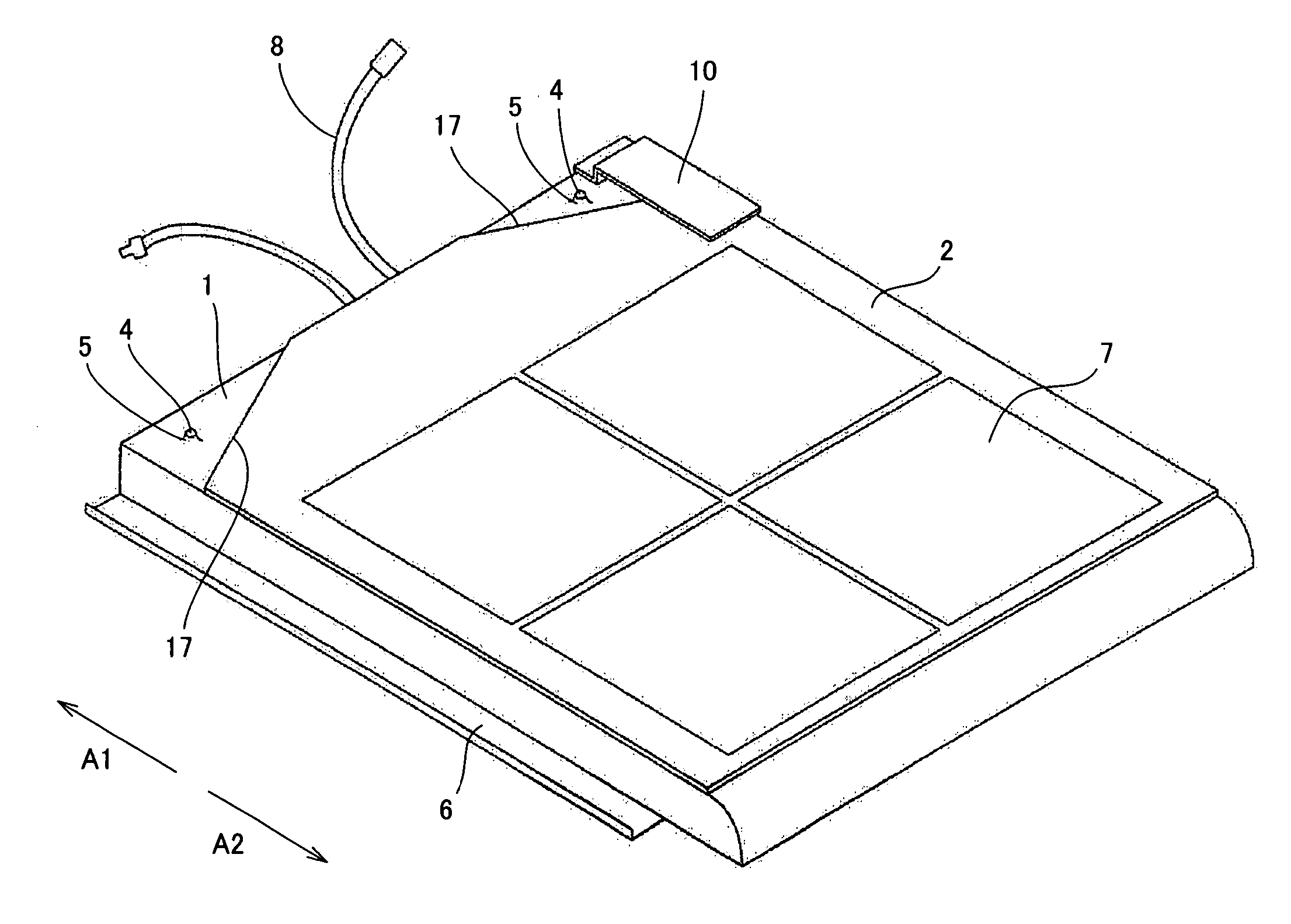
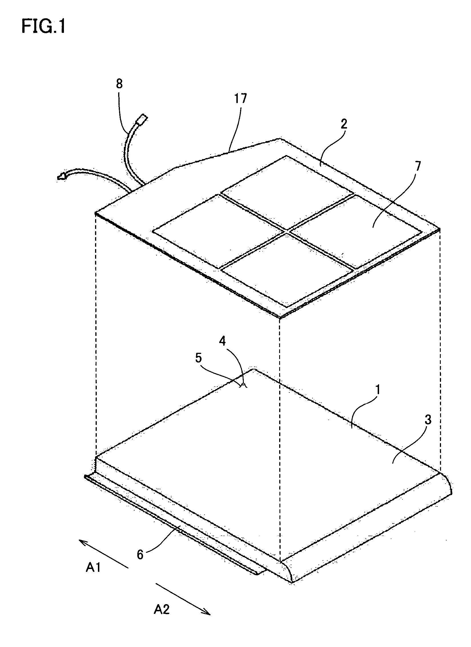
[0030]FIG. 1 shows an example embodiment of roof cover type solar cell module, with the roof cover base member and the power generating unit separated from each other.

[0031]In the present embodiment, description will be made based on a solar cell module having an outer structure that allows mating with a plain roof tile of which working region (i.e., part exposed on the roof surface after installation) has a working width of 305 mm and a working length of 280 mm. The roof cover type solar cell module shown in FIG. 1 is placed on the roof surface so that the direction indicated by an arrow A1 corresponds to the ridge side and the direction indicated by an arrow A2 corresponds to the eaves side.

[0032]In FIG. 1, a roof cover base member 1 is provided with a mounting surface 3 for mounting a power generating unit 2 thereto, and an underlap 6 for mating with an adjacent roof cover such as a roof tile. Roof cover base member 1 may be made of an aluminum plate, stainless steel plate, galva...


PUM


Abstract

A roof cover type solar cell module includes a roof cover base member and a power generating unit. The roof cover base member has a mounting surface to which the power generating unit is mounted, and an underlap that can mate with an adjacent roof cover. The power generating unit is mounted to the mounting surface, leaving a part of the mounting surface uncovered. Thus, a roof cover type solar cell module for which a variety of materials can be used for the roof cover base member, which can be produced at low cost, and which is excellent in stability when placed on the roof surface, and also excellent in workability, weather resistance and design property, is provided.

Description

[0001]This nonprovisional application is based on Japanese Patent Application No. 2003-353615 filed with the Japan Patent Office on Oct. 14, 2003, the entire contents of which are hereby incorporated by reference.BACKGROUND OF THE INVENTION[0002]1. Field of the Invention[0003]The present invention relates to a solar cell module. More particularly, the present invention relates to a solar cell module having an outer structure allowing mating with an adjacent roof cover.[0004]2. Description of the Background Art[0005]To secure a solar cell module to a roof surface, in many cases, a stand is placed on a roof cover at the roof surface, and the solar cell module is secured to the stand. With recent diversification of the users' needs, however, a large number of solar cell modules having a solar cell integrated with a roof cover and excellent in design property have been proposed (see, e.g., Japanese Patent Laying-Open Nos. 11-324234, and 2002-070271).[0006]In many of the proposed solar c...

Claims


Application Information

Patent Timeline
Patent Type & Authority Patents(United States)
IPC IPC(8): H01L31/048E04D1/28E04D1/30E04D13/18E04D3/40H01L25/00H01L31/042
CPCH02S20/25Y02B10/12Y10S136/291Y02B10/10Y02E10/50
Inventor KOMAMINE, TATSUYA
Owner SHARP KK
Why Eureka
Try Eureka