Apparatus and method for mail sorting

a sorting apparatus and mail sorting technology, applied in the field of mail sorting, can solve the problems of inability to adapt to sorting, inconvenient transfer, and inability to sort mail into delivery orders, and achieve the effect of reducing the capacity of the slot and smooth transfer

Inactive Publication Date: 2006-11-21
SIEMENS LOGISTICS LLC
View PDF26 Cites 117 Cited by
  • Summary
  • Abstract
  • Description
  • Claims
  • Application Information

AI Technical Summary

Benefits of technology

[0017]An inserter apparatus according to the invention useful for sorting mail pieces or other articles includes a frame, a pair of inserter plates spaced to receive a mail piece therebetween, a first guide disposed on the frame on which the inserter plates can move from a retracted position to an extended position, an H-shaped belt including two loops united by a lateral connecting portion, the loops being slidably mounted on each of the plates, a first drive system disposed on the frame for moving the plates and belt between the extended and retracted positions, and a second drive system disposed on the frame and connected to the connecting portion of the belt for moving the connecting portion of the belt forward and back along the plates, causing sliding movement of the loops around the outsides of each of the belts, with forward movement being effective to move a mail piece received by the belt ahead of the connecting portion out of a front end opening of the plates, and rearward movement being effective to draw a mail piece received in the front end opening of the plates rearwardly to a position between the plates. The H-shaped belt does not move relative to the mail piece as it is inserted.
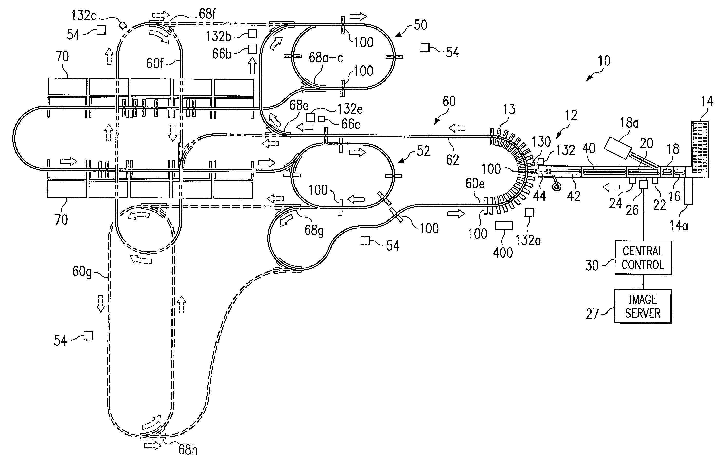
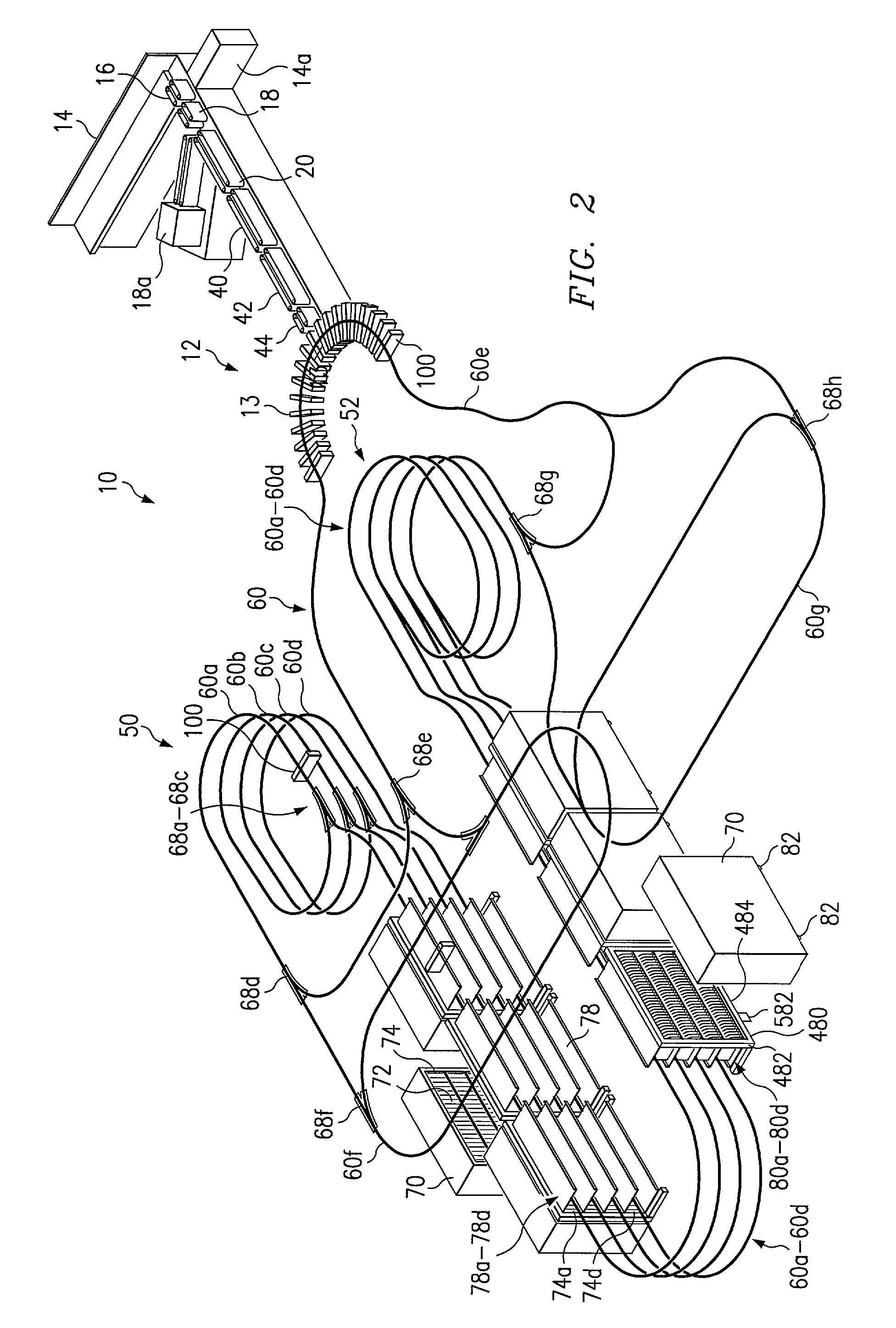
[0018]The invention further provides other innovations related to mail sorting as discussed in the detailed description which follows. For example, spring loaded partitions that can move more than one pitch or slot width allow overfilling and move so that the inserter thickness does not reduce the capacity of the slot. The invention further provides a method and apparatus for simultaneous insertion, packaging, traying, containerizing of mail, and a portable mail case for use in such a method in which mail can be sorted directly into trays. Where plastic bags are mounted in the case instead of using fixed slot dividers, the invention provides a method and apparatus for simultaneous loading into bag, tray, and container (rolling case). The invention further provides a loading system for a delivery robot wherein synchronized moving belts are used to ensure that a mail piece is smoothly transferred from a loading conveyer to the delivery robot. Specifically, controlled loading of a mail piece into an H-belt on the delivery robot is controlled by retraction of a belt drive post to achieve controlled deceleration of the mail piece. Further, since the system of the invention permits sorting to a relatively large number of slots or bags in a relatively compact space, the invention permits single pass sortation of mail in delivery order on a reasonable scale of system size and density. The system of the invention also achieves such sortation without any bending of mail pieces and accommodates mail of varying sizes and thicknesses, i.e., mixed mail. The invention also provides a method and apparatus for single step sorting directly to mail trays positioned in delivery carts, eliminating the traditional steps of manual sorting to a mail case and then pulling down the sorted mail into trays. These and other aspects of the invention are set forth in the detailed description which follows.

Problems solved by technology

This sorting and shuffling through various stacks of mail is time consuming, inefficient, and consequently expensive to the USPS.
However, current mail sorting systems are not adapted to sort and collect mail destined for a single delivery point or address as a discreet group of mail pieces.
Although these machines are capable of sorting mail pieces within a limited size and thickness range, these machines are limited to sorting the mail into delivery order.
Further, a large fraction of mail is not processed with these machines and must be manually sorted, producing a multiplicity of groupings of mail sorted into delivery order.

Method used


Image

  • Apparatus and method for mail sorting
  • Apparatus and method for mail sorting
  • Apparatus and method for mail sorting

Examples


case 700

[0110]Case 700 contains a number of trays 730 which rest side by side on shelves 707, two in center section 702 and one each on wings 704. There are 4 trays per row, 16 total trays when 4 tiers are provided. Each tray comprises a flat bottom 732, a pair of opposed side walls 734 with handholds 735, and a back wall 736, leaving the front open. Shelves 707 may be slightly angled (e.g., about 1–20 degrees) in a rearward direction, so that when trays 730 are placed therein with the front side facing outward as shown, mail tends to remain in the tray by the force of gravity. Trays 730 may be made from molded plastic and fit precisely within the open front of case 700.

[0111]When case 700 is in position for sorting, mail is sorted directly to trays 730. For this purpose, trays may be provided with parallel partition walls that correspond to side walls 71 in case 70. However, this takes up additional space and prevents the mail from being easily removed from the tray 730 by the postal carri...


PUM

PropertyMeasurementUnit
flexibleaaaaaaaaaa
widthsaaaaaaaaaa
distanceaaaaaaaaaa

Abstract

A method for sorting mail to a case having a plurality of slots is described, wherein each slot corresponds to a destination. The method includes steps of loading a mail piece to be sorted into a delivery robot, determining for the mail piece a destination slot the mail piece is to be delivered to, moving the delivery robot along a rail disposed at the front of the case near the slots into proximity with an open end of the destination slot, inserting the mail piece from the delivery robot into the associated slot, and returning the delivery robot to a loading station whereby the cycle may be repeated. Such a method, when using a large number of robots moving along a common rail system, can sort a large volume of mail in carrier delivery order.

Description

[0001]This application claims priority of U.S. Provisional Application No. 60 / 309,402, filed Aug. 1, 2001.TECHNICAL FIELD[0002]The present invention relates to the field of mail sorting, and particularly to an apparatus and method for loading mail pieces into individual receptacles such as slots or pockets.BACKGROUND OF THE INVENTION[0003]Each day more than 200,000 United States Postal Service (USPS) carriers deliver mail to approximately 100 million individual domestic addresses. The mail received and delivered by the USPS generally consists of three broad types of items, namely letters, flat mail that is larger than letter mail, and parcels. The term “letter” is generally used to refer to postcards, standard sized letters and mail pieces of similar dimensions, whereas the term “flat” is generally used to refer to magazines, catalogues and similar, larger mail pieces. Before a carrier begins to walk or drive through his or her delivery route, it is the carrier's responsibility to p...

Claims


Application Information

Patent Timeline
Patent Type & Authority Patents(United States)
IPC IPC(8): B07C5/00B65G1/133B07C3/02B07C3/08
CPCB07C3/02B07C3/087B65H29/14B65H29/60B65H31/02B65H31/24B65H39/115B65H2405/20B65H2405/3521B65H2408/11B65H2801/78B65H2301/321B65H2301/4214B65H2301/424B65H2404/2615Y10S209/90
Inventor PIPPIN, JAMES M.WORTH, II, FLOYD W.REDFORD, DALE E.KECHEL, OTTMAR K.MONDIE, GEORGE R.ISAACS, GERALD A.
Owner SIEMENS LOGISTICS LLC
Why Eureka
Try Eureka