
Method and apparatus to set a tuning range for an analog delay

a technology of analog delay and tuning range, which is applied in the direction of pulse automatic control, pulse manipulation, pulse technique, etc., can solve the problems of pronounced jitter in the output clock or undesired skew between the feedback clock, analog dlls have a relatively narrow locking range and relatively long lock time compared to digital dlls, and analog fine adjustment may contain its own set of tuning problems, etc., to achieve a substantial fine tuning range

Active Publication Date: 2006-11-21
MICRON TECH INC
View PDF18 Cites 21 Cited by
  • Summary
  • Abstract
  • Description
  • Claims
  • Application Information

AI Technical Summary

Benefits of technology

Enables a substantial fine tuning range and maintains phase lock across PVTF variations, reducing jitter and skew by allowing continuous and responsive delay adjustments.

Problems solved by technology

However, they have the disadvantage of pronounced jitter in the output clock or an undesired skew between the feedback clock and the reference clock due to the availability of only discrete time adjustments in increments of the delay through a single delay element.
However, the result of the phase comparison is a bias voltage, which may move up or down.
However, Analog DLLs have a relatively narrow locking range and relatively long lock time compared to digital DLLs.
However, analog fine adjustment may contain its own set of tuning problems.
Conventionally, it has not been possible, using analog delay lines, to adjust across all operational corners of variations in Process, Voltage, Temperature, and Frequency of the output clock (PVTF).
If the bias voltage for the fine tuning is not set initially at a value allowing substantial tuning range in both directions, coarse digital corrections may be required introducing undesired jitter.

Method used


Image

  • Method and apparatus to set a tuning range for an analog delay
  • Method and apparatus to set a tuning range for an analog delay
  • Method and apparatus to set a tuning range for an analog delay

Examples


Embodiment Construction

[0026]In the following description, circuits and functions may be shown in block diagram form in order not to obscure the present invention in unnecessary detail. Conversely, specific circuit implementations shown and described are exemplary only, and should not be construed as the only way to implement the present invention unless specified otherwise herein. Additionally, block definitions and partitioning of logic between various blocks is exemplary of a specific implementation. It will be obvious to one of ordinary skill in the art that the present invention may be practiced by numerous other partitioning solutions. For the most part, details concerning timing considerations and the like have been omitted inasmuch as such details are not necessary to obtain a complete understanding of the present invention and are within the abilities of persons of ordinary skill in the relevant art.

[0027]The term “bus” is used to refer to a plurality of signals or conductors, which may be used t...


PUM


Abstract

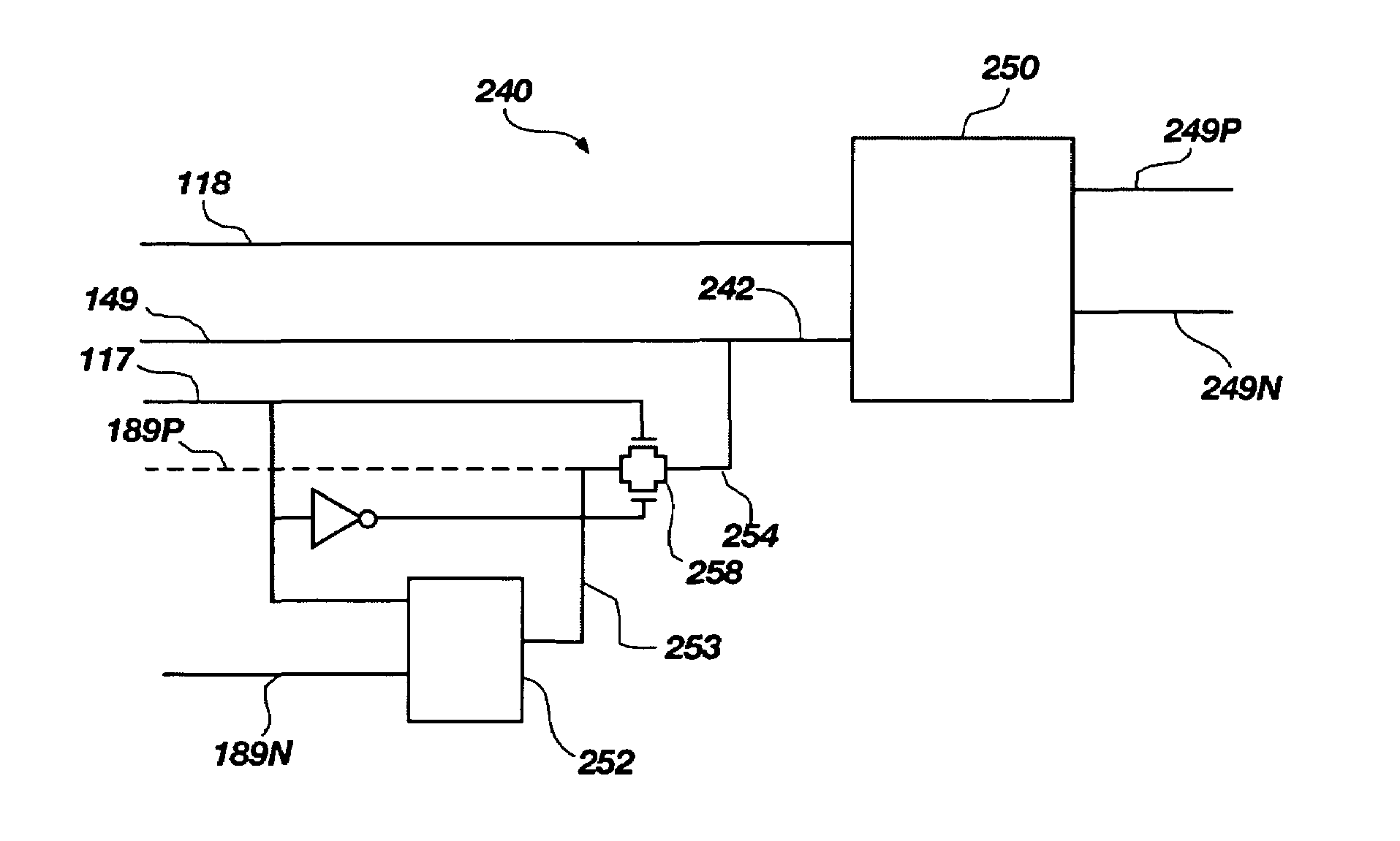
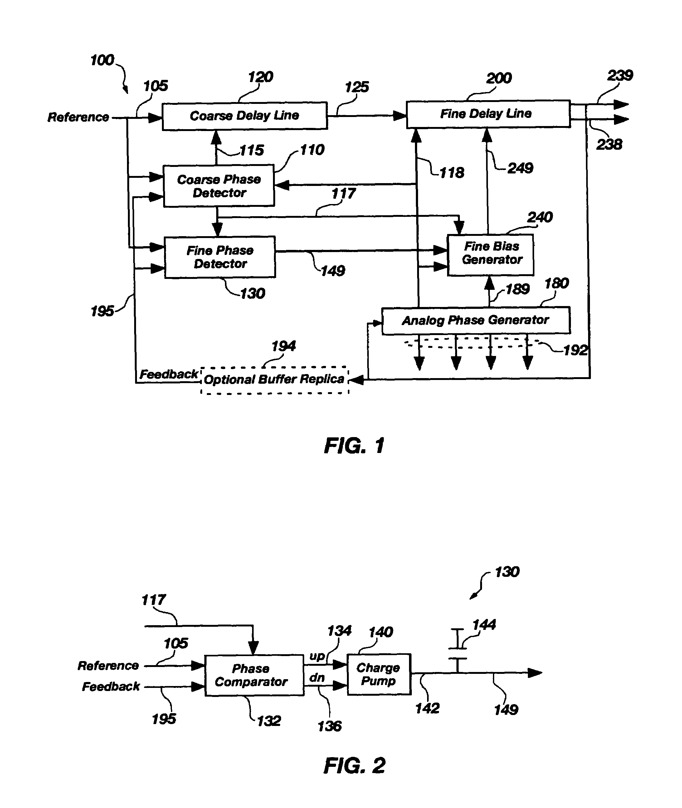
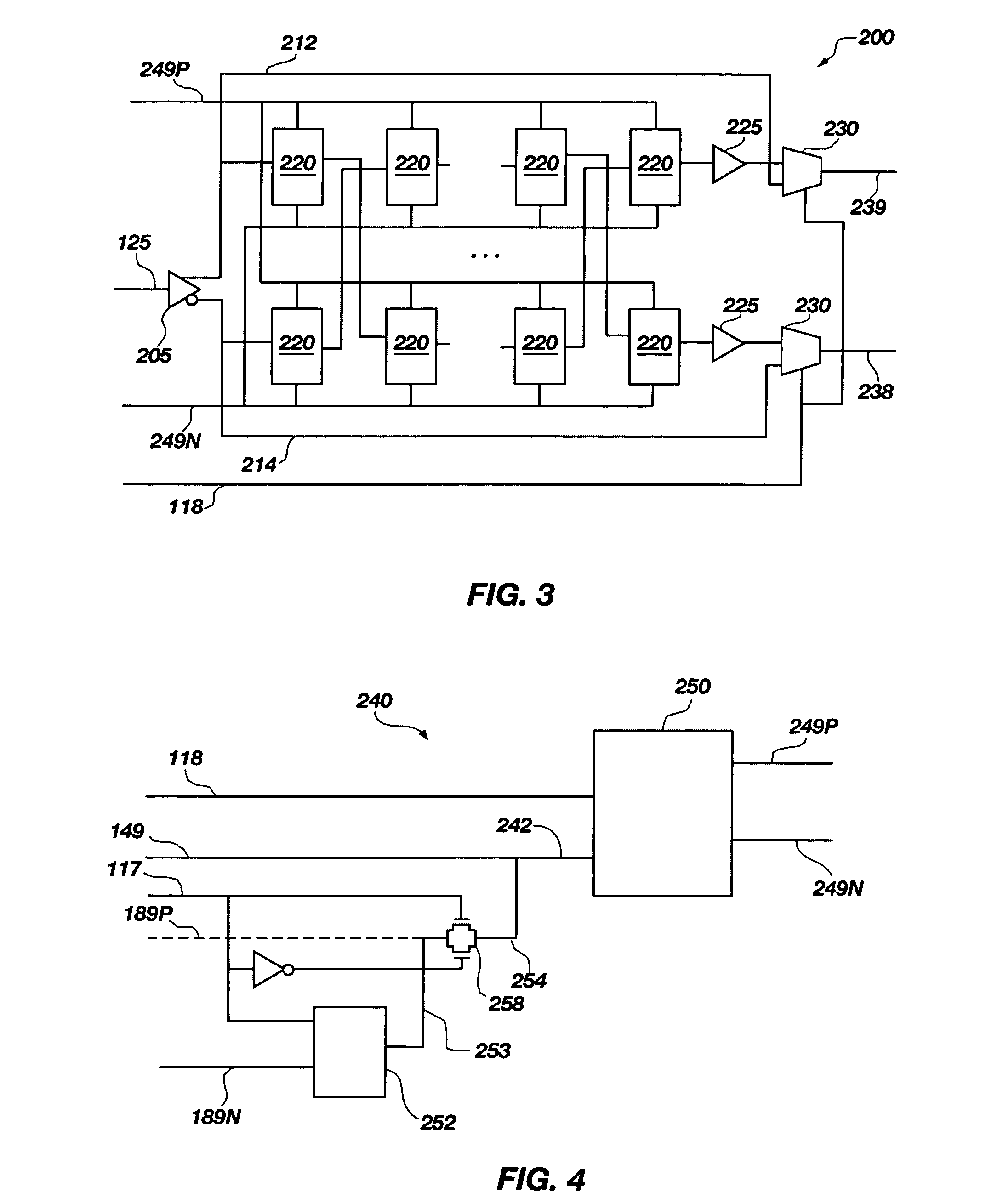
An apparatus and method for an analog fine delay line, a hybrid delay line, and a delay locked loop (DLL) is described. In the DLL, a coarse phase detector compares a reference signal and feedback signal in controlling coarse phase adjustment signals indicating whether a delay of a coarse delay line should be increased or decreased. Similarly, a fine phase detector compares the reference signal and feedback signal to generate a locking bias signal, which may increase or decrease a delay of an analog fine delay line. The analog fine delay line and coarse delay line may be connected in series creating the hybrid delay line having a total delay comprised of the coarse delay and the fine delay. Additionally, a fine bias generator may control the fine delay in response to an initiating bias signal from an analog phase generator or the locking bias signal.

Description

BACKGROUND OF THE INVENTION[0001]1. Field of the Invention[0002]This invention relates generally to mixed delay lines, and particularly to analog delay circuits and methods for setting a tuning range of the analog delay circuits.[0003]2. Description of Related Art[0004]In modern high frequency integrated circuits, it is often necessary to generate internal clocks with predetermined phase relationships to a reference clock. Conventionally, a Phase Locked Loop (PLL) or Delay Locked Loop (DLL) has been used to generate this predetermined phase relationship. A variety of reasons may exist for requiring the phase relationship. For example, it may be desirable to adjust an internal clock relative to a reference clock to minimize delay between the reference clock and output signals controlled by the internal clock. In another example, it may be desirable to minimize skew or eliminate delay between the reference clock and an internal clock buffered by a large internal clock tree. A PLL or D...

Claims


Application Information

Patent Timeline
Patent Type & Authority Patents(United States)
IPC IPC(8): H03H11/26
CPCH03H11/265H03L7/0812H03L7/0814H03L7/087H03L7/0818H03K5/133H03K2005/00026H03L7/0816H03L7/06H03L7/081
Inventor LIN, FENG
Owner MICRON TECH INC
Learn More