Distributed clock network using all-digital master-slave delay lock loops

a clock network and slave slave technology, applied in the field of digital communication, can solve the problems of poor clock driver and data driver skew, and low data transfer speed, and achieve the effect of improving the setup and hold times, reducing the cost of hardware and software maintenance, and improving the reliability of hardware and softwar

Active Publication Date: 2006-11-21
MACOM CONNECTIVITY SOLUTIONS LLC
View PDF11 Cites 19 Cited by
  • Summary
  • Abstract
  • Description
  • Claims
  • Application Information

AI Technical Summary

Problems solved by technology

The setup and hold time windows on high speed data lines can be degraded by clock driver and data driver skew, duty cycle distortion of data drivers, clock and data jitter, and power supply noise.
Hig

Method used


Image

  • Distributed clock network using all-digital master-slave delay lock loops
  • Distributed clock network using all-digital master-slave delay lock loops
  • Distributed clock network using all-digital master-slave delay lock loops

Examples


Embodiment Construction

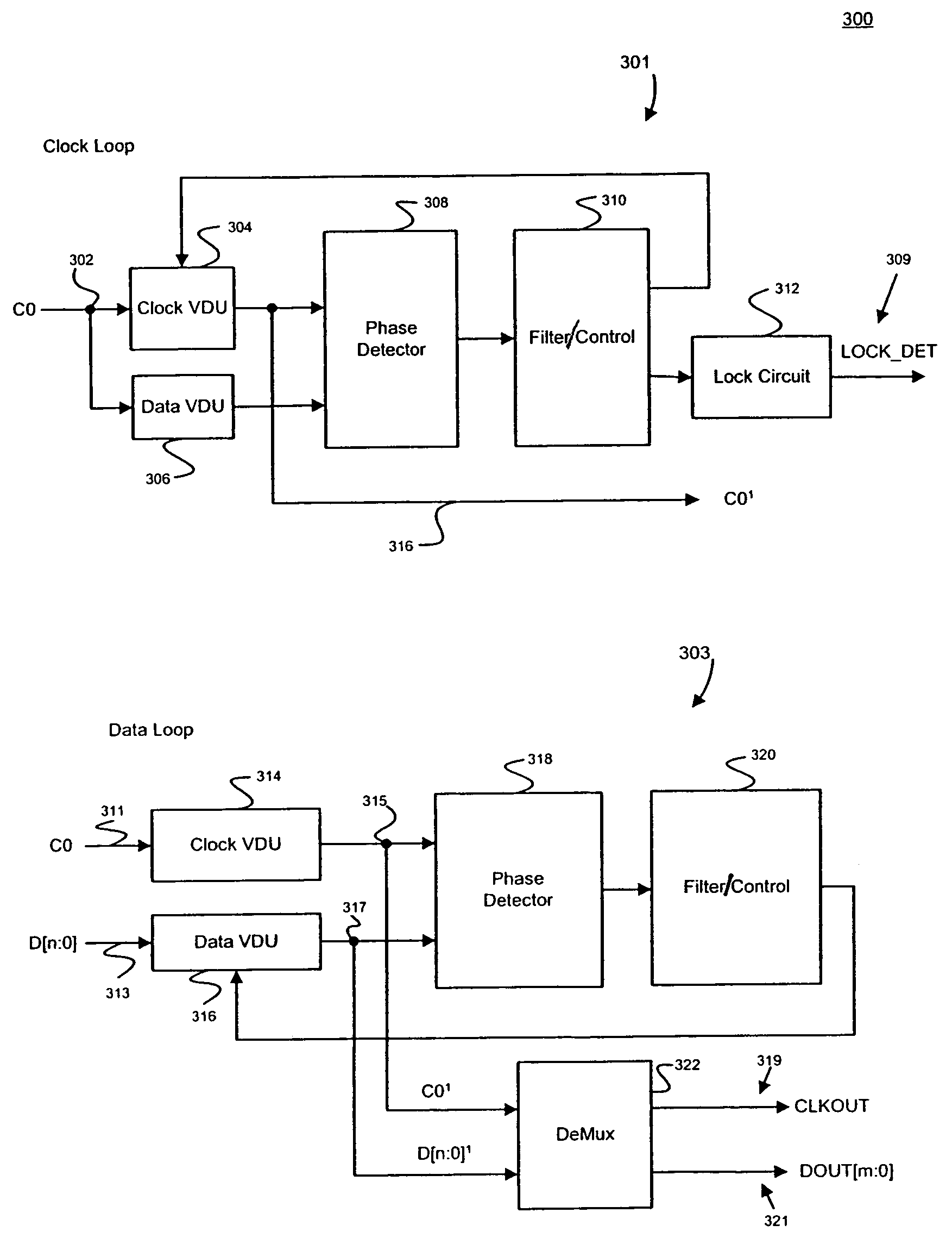
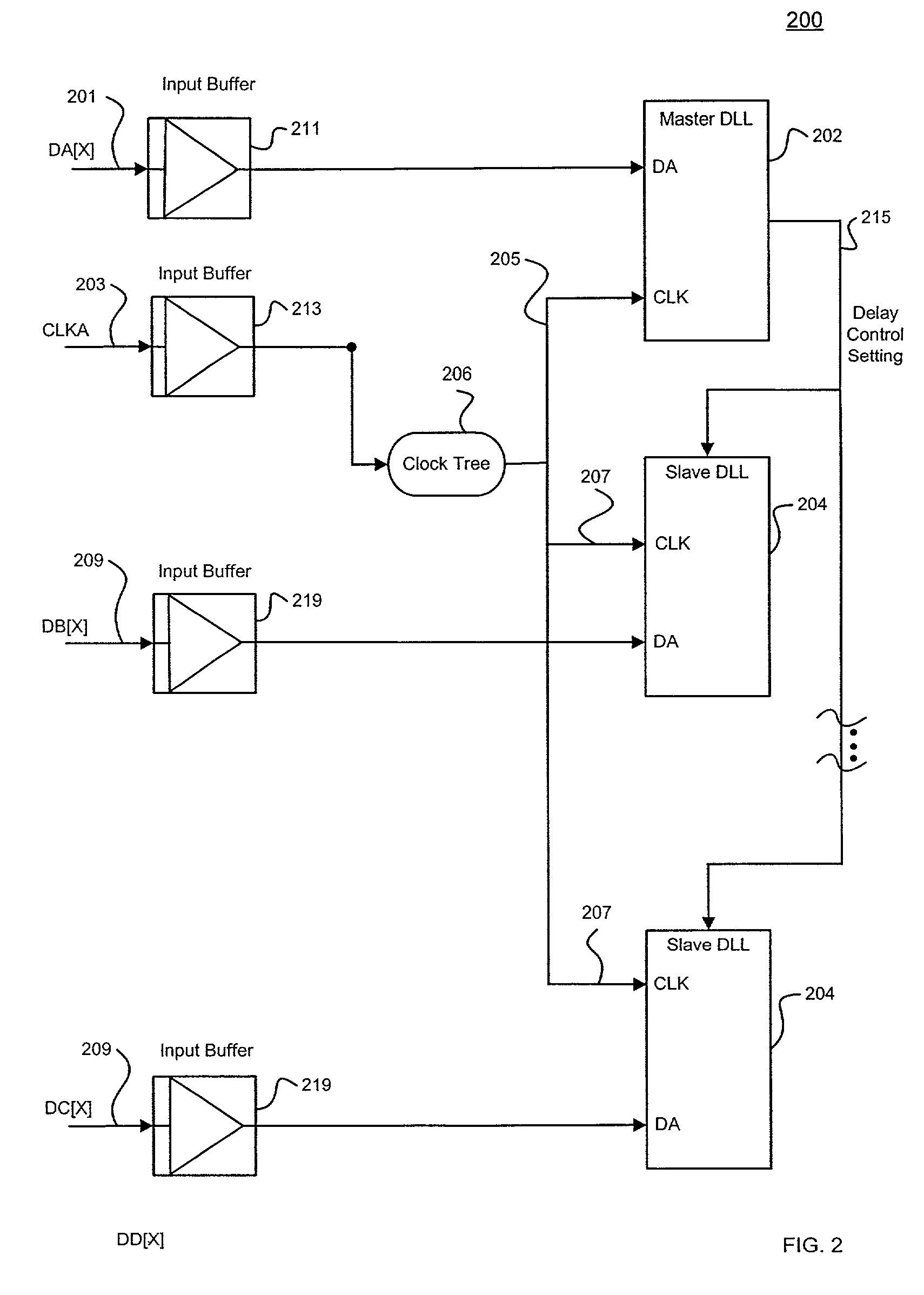
[0008]This invention provides a clock distribution network using an all-digital delay lock loop architecture. In one example, the clock distribution network is implemented on a chip to distribute clock information to various physical locations on the chip. In an exemplary embodiment, a distributed clock circuit for distributed high speed data includes a master delay lock loop (DLL) circuits and one or more slave DLL circuits. The slave DLL circuits are distributed physically around to various locations on the chip. The master DLL circuit is configured to lock a global clock signal with a first data signal, and output a clock delay control signal when the global clock signal is locked. The one or more slave DLL circuits are coupled to receive the clock delay control signal to lock a local clock signal with a local data signal. In the preferred embodiment, the local clock signal is based on the global clock signal.

[0009]In the example, the master DLL circuit includes a master clock DL...


PUM


Abstract

A distributed clock circuit for clocking high speed data at various different physical locations on a chip while improving setup and hold times. The clock circuit includes a master delay lock loop (DLL) circuit configured to lock a global clock signal with a first data signal, and output a clock delay control signal when the global clock signal is locked. The clock circuit further includes one or more slave DLL circuits, coupled to receive the clock delay control signal to lock a local clock signal with a local data signal, wherein the local clock signal is based on the global clock signal.

Description

BACKGROUND OF THE INVENTION[0001]The present invention generally relates to digital communications, and more particularly to a delay lock loop (DLL) circuit for improving setup and hold times for a parallel data communication system.[0002]Digital communications promises faster, flexible, and more reliable speeds than conventional analog communications. Accordingly, various time measurements become critical. For instance, in a digital communication system, setup time represents the length of time that a pulse is held in order to produce a state change. Hold time represents the length of time a signal is maintained at a certain input after changing state at another input. Low setup and hold times are important, especially for high speed parallel data.[0003]The setup and hold time windows on high speed data lines can be degraded by clock driver and data driver skew, duty cycle distortion of data drivers, clock and data jitter, and power supply noise. High speed data from different phys...

Claims


Application Information

Patent Timeline
IPC IPC(8): H03D3/24G06F1/12H03L7/06
CPCH03L7/07H03L7/0805H03L7/0814H04L7/033H04L7/0037H03L2207/50H04L7/0008H04L7/0041
Inventor FU, WEIBALARDETA, JOSEPH J.
Owner MACOM CONNECTIVITY SOLUTIONS LLC
Why Eureka
Try Eureka