Use of boron or enriched boron 10 in UO2

a technology of boron and uo2, which is applied in the direction of nuclear elements, greenhouse gas reduction, reactor fuel susbtance, etc., can solve the problems of limiting the amount of coating that can be contained within each rod, high overhead costs, and the cost of coating the pellets is high, so as to avoid the problem of pressurization, reduce the parasitic cross-section, and reduce the cost

Inactive Publication Date: 2006-11-21
WESTINGHOUSE ELECTRIC CORP
View PDF20 Cites 29 Cited by
  • Summary
  • Abstract
  • Description
  • Claims
  • Application Information

AI Technical Summary

Benefits of technology

[0011]The present invention solves the above need by providing a fuel assembly comprising a plurality of fuel rods, each fuel rod containing a plurality of nuclear fuel pellets, wherein at least one fuel pellet in more than 50% of the fuel rods in the fuel assembly comprises a sintered admixture of an actinide oxide, actinide carbide or actinide nitride and a boron-containing compound. Due to the fact that boron has a relatively low parasitic cross-section as compared to other burnable absorbers, it will typically be necessary to put boron-containing fuel pellets in more than 50% of the rods. It has been found, contrary to previous assumptions, that boron does not interact with the nuclear fuel, and is not the primary cause of pressure in the fuel rods, when the amount of helium produced is compared to the amounts of other fission gases released during fuel use. Preparing fuel with an admixture of boron is much less expensive. Therefore, a greater number of rods can have the boron-containing fuel pellets, providing a greater amount of boron in the core but with less boron in each rod, thus avoiding the pressurization problem. For example, with the use of coated pellets fuel rods will contain about 2 mg boron per inch, whereas with the use of boron directly in the pellet fuel rods will contain about 1–1.5 mg boron per inch, a 25–50% reduction.
[0012]By adding either natural or enriched boron to at least one fuel pellet in a majority of the rods in a fuel assembly, reactivity hold-down that is equivalent or superior to that provided by current methods is provided, at much lower cost. Additionally, increasing the number of rods containing boron can reduce the internal fuel rod pressure by a factor of 2 or 3 over that found in current practice. Thus, using lower levels of a boron-containing compound, in combination with its distribution more widely among the fuel rods, provides the benefits of the present invention. As will be appreciated by one skilled in the art, these benefits are most advantageous when the thermal output of the reactor core is above 500 megawatts thermal, in the case of water-cooled reactors, or above 200 megawatts thermal in the case of gas-cooled reactors.
[0013]The use of boron in boiling water reactor fuel as a substitute for the currently employed Gd2O3 and Er2O3 provides even greater benefits. In addition to simplifying manufacturing and reducing rod pressurization, the space that is taken up by the Gd2O3 and Er2O3 in the fuel pellets can be replaced by more UO2 (or other actinide oxide, carbide or nitride), thus allowing more fuel to be loaded in a given size core. Enrichment constraints currently applied on a rod-by-rod basis due to poor thermal conductivity of these rare-earth oxides can be completely avoided, thus yielding a significant simplification in the manufacture of nuclear fuels.

Problems solved by technology

However, nuclear fuel pellets containing an admixture of a boron burnable absorber with the fuel have not been used in large land-based reactors due to concerns that boron would react with the fuel, and because the use of boron was thought to create high internal rod pressurization from the accumulation of helium in the reaction:
However, this does not solve the pressurization problem, which limits the amount of coating that can be contained within each rod.
More rods with a lower 10B loading must be used, thus necessitating the handling and coating of a large number of fuel pellets, which is very expensive and results in high overhead costs.
In practice, the cost of coating the pellets limits their use, and they are used in as few rods as possible, taking into account the pressurization problem described above.
Neither disclose assembly arrangements suitable for reactors producing over 500 megawatts thermal power.

Method used


Image

  • Use of boron or enriched boron 10 in UO2
  • Use of boron or enriched boron 10 in UO2
  • Use of boron or enriched boron 10 in UO2

Examples


Embodiment Construction

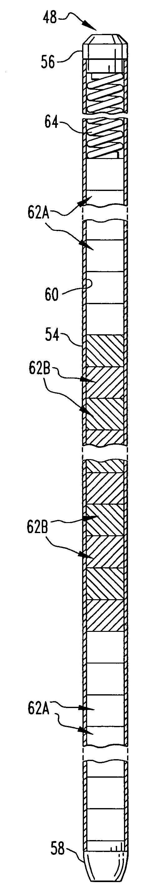
[0019]Accordingly, the present invention provides a fuel assembly comprising a plurality of fuel rods, each fuel rod containing a plurality of nuclear fuel pellets, wherein at least one fuel pellet in more than 50% of said fuel rods in said fuel assembly comprises a sintered admixture of a metal oxide or metal nitride and a boron-containing compound. The boron-containing compound functions as the burnable poison in the fuel. The term “fuel pellet” is used herein to denote the individual sintered pellets of fuel that are loaded into a fuel rod. Preferably, at least one fuel pellet in more than 60% of the fuel rods in the fuel assembly contains a boron-containing compound. Even more preferably, at least one fuel pellet in more than 70–80% of the fuel rods in the fuel assembly contains a boron-containing compound.

[0020]When referring to any numerical range of values herein, such ranges are understood to include each and every number and / or fraction between the stated range minimum and ...


PUM

PropertyMeasurementUnit
thermal poweraaaaaaaaaa
heataaaaaaaaaa
sizeaaaaaaaaaa

Abstract

The present invention provides a nuclear fuel assembly, where a boron-containing compound is used as a burnable poison and is distributed in a majority of the rods in the assembly. The assembly comprises a plurality of fuel rods, each fuel rod containing a plurality of nuclear fuel pellets, wherein at least one fuel pellet in more than 50% of the fuel rods in the fuel assembly comprises a sintered admixture of a metal oxide, metal carbide or metal nitride and a boron-containing compound.

Description

FIELD OF THE INVENTION[0001]The present invention relates to a nuclear fuel assembly, to be used in a nuclear power reactor. The fuel assembly contains fuel pellets having a boron-containing compound in admixture with the nuclear fuel.BACKGROUND INFORMATION[0002]In a typical nuclear reactor, such as a pressurized water (PWR), heavy water or a boiling water reactor (BWR), the reactor core includes a large number of fuel assemblies, each of which is composed of a plurality of elongated fuel elements or rods. The fuel rods each contain fissile material such as uranium dioxide (UO2) or plutonium dioxide (PUO2), or mixtures of these, usually in the form of a stack of nuclear fuel pellets, although annular or particle forms of fuel are also used. The fuel rods are grouped together in an array which is organized to provide a neutron flux in the core sufficient to support a high rate of nuclear fission and thus the release of a large amount of energy in the form of heat. A coolant, such as ...

Claims


Application Information

Patent Timeline
Patent Type & Authority Patents(United States)
IPC IPC(8): G21C3/00
CPCG21C3/58G21C3/62Y02E30/38Y10S376/901Y02E30/30
Inventor LAHODA, EDWARD J.
Owner WESTINGHOUSE ELECTRIC CORP
Why Eureka
Try Eureka