Method for enhancing the contrast of an image
a technology of contrast enhancement and image, applied in image enhancement, image analysis, instruments, etc., can solve the problems of high time-consuming and laborious determination of optimal parameters for each examination type, more error-prone identification than the ris system, and large limitation of the use of computed radiography systems
- Summary
- Abstract
- Description
- Claims
- Application Information
AI Technical Summary
Benefits of technology
Problems solved by technology
Method used
Image
Examples
second embodiment
[0150]In a second embodiment another criterion is applied.
[0151]According to this second criterion the aim is to bring the noise level to a constant target value in accordance with the formula Gn=Tn / σ0n wherein Gn is a normalisation factor, Tn represents the target noise level and σ0n is the estimated noise level.
[0152]The resulting normalisation factor is applied to all pixel values.
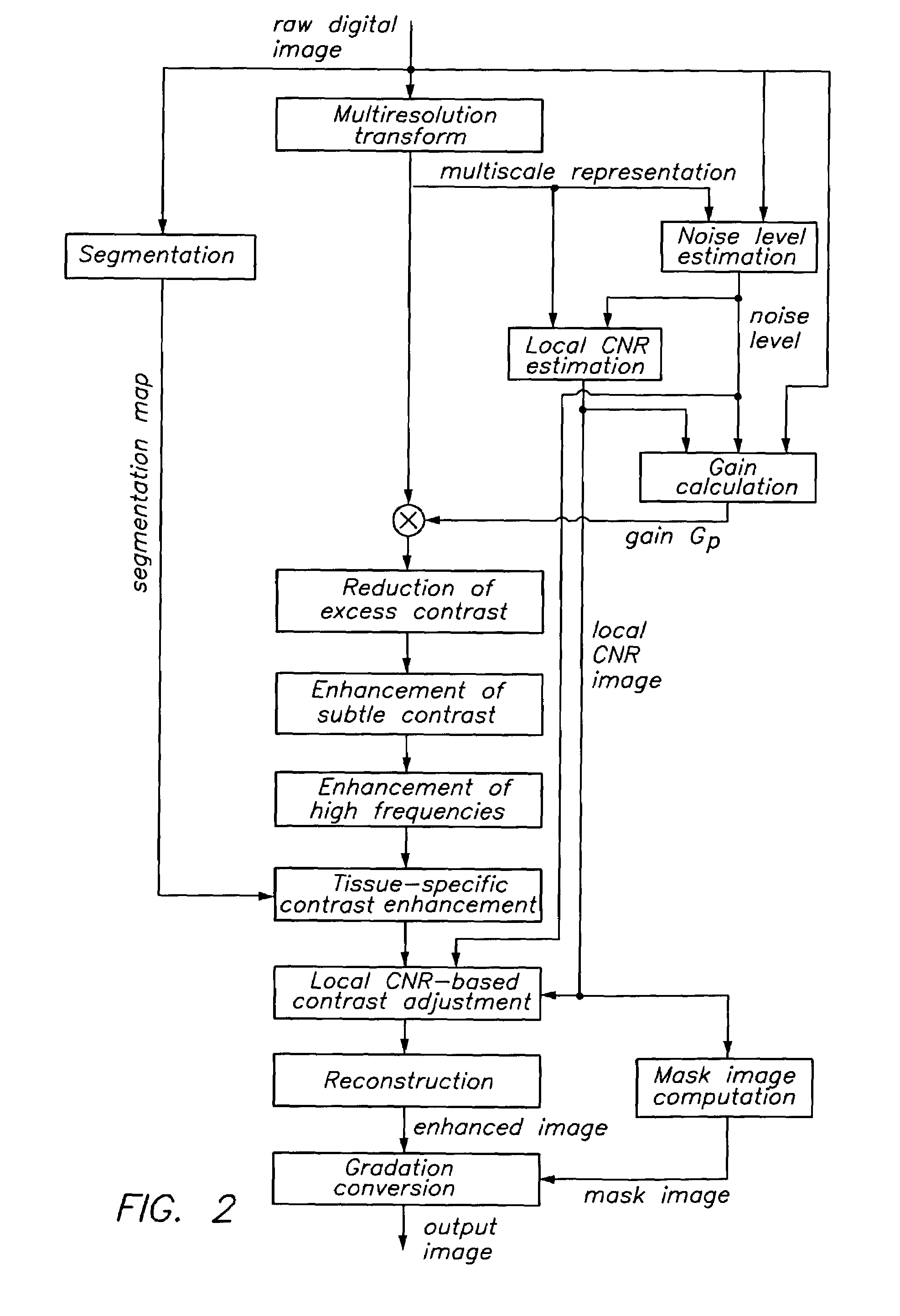
[0153]The noise level is preferably estimated on the basis of the finest scale of the multi-resolution representation of the image, as described above.
[0154]This second criterion results in a uniform impression of noise in all images.
[0155]However, if a different read out sensitivity is chosen, this has an influence on the contrast. Setting sensitivity low (e.g. sensitivity class 100) may result in a contrast which is too explicit, while setting the sensitivity class high (e.g. sensitivity class 400) may result in a contrast which is too weak.
c) Third Criterion: Constant Contrast
third embodiment
[0156]In a third embodiment a still different criterion is applied. According to this criterion the aim is to bring the contrast of the most relevant area in the image to a constant level in accordance with the formula Gc=Tc / σc wherein Gc is a normalisation factor, Tc is the envisaged contrast level and σc is the original contrast.
[0157]This intrinsic image parameter is somewhat arbitrary because contrast highly varies in the image. The average contrast is not representative because the influence of homogeneous regions (having very low contrast) and of strong border pixels (having large contrast) would be dominating.
[0158]The original contrast is determined by computing the histogram of local standard deviation at a predefined scale that is sufficiently large to avoid predominance of noise, preferably at the fourth scale when scales are counted from fine to coarse. The original contrast σc is defined as the median value of the local standard deviations in the histogram. The histogra...
first embodiment
[0206]In a first embodiment sharpening is realised by pixelwise multiplying the layers of the normalised multiscale representation with a coefficient that depends upon the scale.
[0207]The coefficient is greater than one at the finest scale (scale 0), and it gradually decreases to a value of one at the medium scales, and it further remains one at the larger scales.
[0208]In a second embodiment, the image is sharpened by making the parameter b that determines the contrast enhancement of subtle details dependent on the scale. This is realised according to the present invention by giving the parameter b a maximum value at scale 0, and by decreasing the value of this parameter b according to a geometric series at medium scales and then further keeping the parameter constant at the larger scales.
[0209]In comparison with the first embodiment of sharpening, the approach of this second embodiment provides that the amplification of small-scale detail is only exerted in points having subtle con...
PUM
 Abstract
Description
Claims
Application Information
 - R&D
- Intellectual Property
- Life Sciences
- Materials
- Tech Scout
- Unparalleled Data Quality
- Higher Quality Content
- 60% Fewer Hallucinations
Browse by: Latest US Patents, China's latest patents, Technical Efficacy Thesaurus, Application Domain, Technology Topic, Popular Technical Reports.
© 2025 PatSnap. All rights reserved.Legal|Privacy policy|Modern Slavery Act Transparency Statement|Sitemap|About US| Contact US: help@patsnap.com


