Nonlinear device comprising a spectrally broadening fiber

a spectrally broadening fiber and optical fiber technology, applied in the direction of optical elements, transmission monitoring, instruments, etc., can solve the problems of increasing the bit error rate (ber) of the system, and the magnitude of these effects is not always known in advance, so as to improve the system performance

Inactive Publication Date: 2006-11-21
FURAKAWA ELECTRIC NORTH AMERICA INC
View PDF9 Cites 9 Cited by
  • Summary
  • Abstract
  • Description
  • Claims
  • Application Information

AI Technical Summary

Benefits of technology

[0007]The invention is embodied in a system for monitoring the effectiveness of pulse shaping in a nonlinear optical fiber. More specifically, according to embodiments of the invention, the spectral content of the pulse, after passing through the nonlinear fiber, provides a useful indication of how effectively the pulse was regenerated. Thus, according to the invention in a broad aspect, a portion of the pulse exiting the nonlinear fiber is tapped off, and a measurement is made of the pulse energy in at least one selected spectral region. The selected spectral region is one in which the pulse tends to gain energy when effective regeneration is taking place.
[0008]In specific embodiments of the invention, the selected spectral region is defined by the output filter of a Mamyshev regenerator. In such embodiments, one useful approach is to compare the pulse energy just after the output filter to the pulse energy just before the output filter. In other specific embodiments of the invention, the tapped off pulse energy is directed into an optical spectrum analyzer adapted to measure the energy in at least one spectral region such as a narrow band about a selected wavelength.
[0009]In another aspect, the embodiments of the invention involve an optical communication system in which the information concerning the effectiveness of pulse shaping in a nonlinear optical fiber is fed back in order to dynamically change the residual dispersion at the regenerator input. Even more broadly, the spectral measurement described above can lead to a control signal to indicate a level of performance of the system, or to improve the performance of the system by adjusting an operational parameter. Operational parameters that may be adjusted in this manner include the tuning of a tunable dispersion compensator situated before the nonlinear fiber, the gain of one or more optical amplifiers associated with the regenerator or situated elsewhere in the system, and the tuning of the output filter of the regenerator.

Problems solved by technology

However, noise, chromatic dispersion, and other effects tend to spread the pulses out and to obscure the distinction between pulse and background.
This, in turn, tends to drive up the Bit Error Rate (BER) of the system.
However, the magnitude of these effects is not always known in advance.

Method used


Image

  • Nonlinear device comprising a spectrally broadening fiber
  • Nonlinear device comprising a spectrally broadening fiber
  • Nonlinear device comprising a spectrally broadening fiber

Examples


Embodiment Construction

[0022]In the following description similar components are referred to by the same reference numeral to simplify the sequential aspect of the drawings and / or to enhance the understanding of the invention through the description of the drawings. Also, unless otherwise explicitly specified herein, the drawings are not drawn to scale.

[0023]Although specific features, configurations and arrangements are discussed hereinbelow, it should be understood that such is done for illustrative purposes only. A person skilled in the relevant art will recognize that other steps, configurations and arrangements are useful without departing from the spirit and scope of the invention.

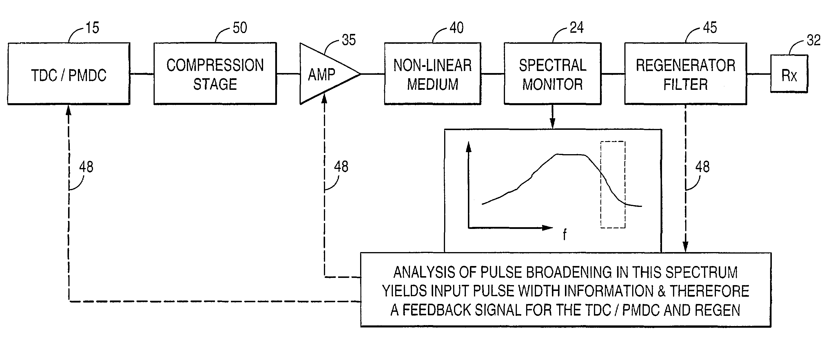
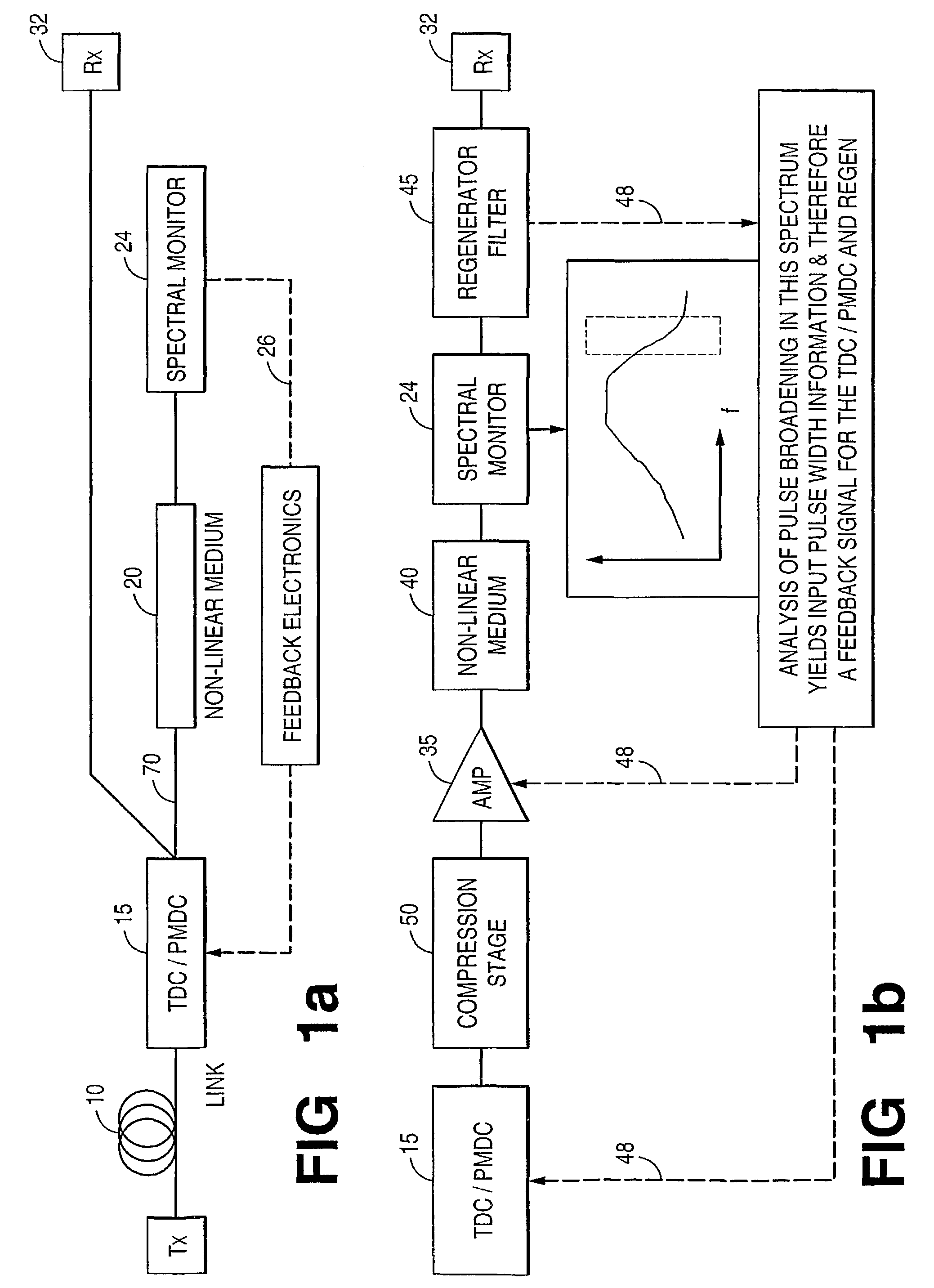
[0024]The optical communication systems of FIGS. 1a and 1b includes communication optical fiber 10, tunable dispersion compensator 15, optical amplifier 20, regenerator 25, output optical fiber 30, and receiver 32. Regenerator 25 includes optical amplifier 35, highly nonlinear fiber 40, and output filter 45. Typical charac...


PUM


Abstract

Embodiments of the invention include system for monitoring the effectiveness of pulse shaping in a nonlinear optical fiber (40). The spectral content of the pulse, after passing through the nonlinear fiber (40), provides an indication of how effectively the pulse was regenerated. A portion of the pulse exiting the nonlinear fiber is tapped off and its pulse energy is measured in at least one selected spectral region. The selected spectral region is one in which the pulse tends to gain energy when effective regeneration is taking place. The information concerning the effectiveness of pulse shaping in a nonlinear optical fiber is fed back to dynamically change the residual dispersion at the regenerator input. The spectral measurement leads to a control signal (48) to indicate a level of performance of the system, or to improve the performance of the system by adjusting an operational parameter.

Description

FIELD OF THE INVENTION[0001]The invention relates to pulse shaping techniques in optical fiber communication systems. More particularly, the invention relates to the use of non-linear optical behavior to restore degraded optical pulses.BACKGROUND OF THE INVENTION[0002]In high-speed optical fiber communication systems, digital data are transmitted in the form of optical pulses propagating in the fiber. An ideal pulse is well localized within a time window and has a well-defined amplitude that stands out distinctly from a low background level. However, noise, chromatic dispersion, and other effects tend to spread the pulses out and to obscure the distinction between pulse and background. These effects can lead to the misinterpretation of high pulse levels (e.g., “ones” in a binary system) as low levels (e.g., as “zeroes” in a binary system) and vice versa. This, in turn, tends to drive up the Bit Error Rate (BER) of the system.[0003]Practitioners have devised regenerators for optical ...

Claims


Application Information

Patent Timeline
Patent Type & Authority Patents(United States)
IPC IPC(8): H04B10/08H04B10/02H04B10/00H04B10/17H04B10/18
CPCH04B10/077H04B10/07955H04B10/2569H04B10/299
Inventor EGGLETON, BENJAMIN J.HER, TSING HUAHUNSCHE, STEFANRAYBON, GREGORYROGERS, JOHN A.WESTBROOK, PAUL S.
Owner FURAKAWA ELECTRIC NORTH AMERICA INC
Why Eureka
Try Eureka