Surgical navigation systems including reference and localization frames
What is Al technical title?
Al technical title is built by PatSnap Al team. It summarizes the technical point description of the patent document.
a navigation system and reference technology, applied in the field of surgical navigation systems including reference and localization frames, can solve the problems of encircling the body part being imaged, affecting the performance of procedures, and affecting the accuracy of the image, etc., and preventing the dedication of a unit for the performance of procedures
Inactive Publication Date: 2006-11-21
SURGICAL NAVIGATION TECH +1
View PDF192 Cites 347 Cited by
Summary
Abstract
Description
Claims
Application Information
AI Technical Summary
This helps you quickly interpret patents by identifying the three key elements:
Problems solved by technology
Method used
Benefits of technology
[0011]It is a further object of this invention to provide a system which can localize a semi-rigid body that may deform between imaging and a procedure and provide a display during the procedure of the body in its deformed shape.
[0023]It is a further object of this invention to provide a system which can localize a body element and provide a display during the procedure of the position of the body element relative to an instrument, such as a forceps, microscope, or laser, so that the instrument can be precisely located relative to the body element.
Problems solved by technology
The majority of the advances in diagrammatic imaging involve devices which tend to be large, encircle the body part being imaged, and are expensive.
Although the scans produced by these devices depict the body part under investigation with high resolution and good spatial fidelity, their cost usually precludes the dedication of a unit to be used during the performance of procedures.
Method used
Image
Click on the blue label to locate the original text in one second.
Reading with bidirectional positioning of images and text.
Examples
Embodiment Construction
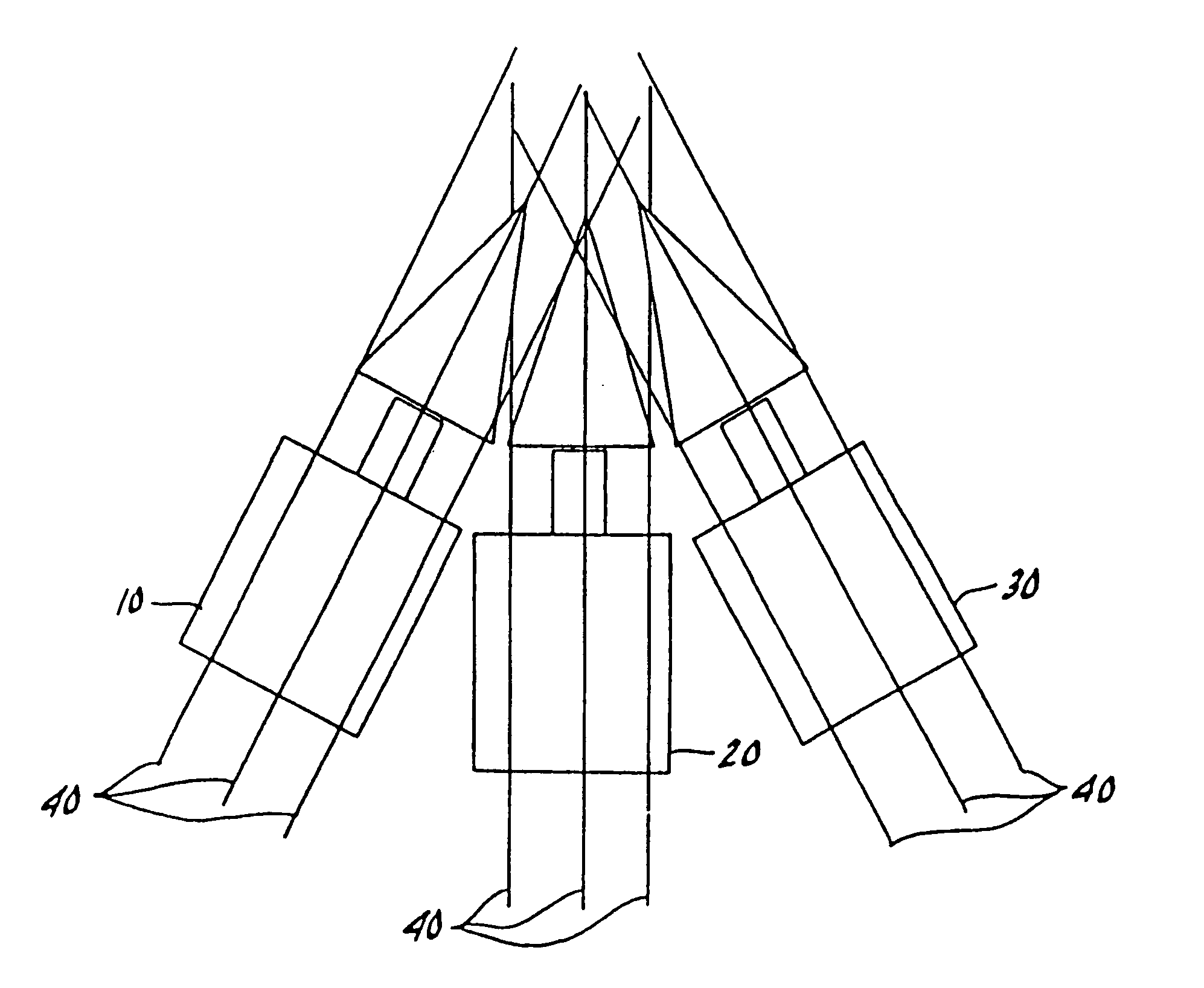
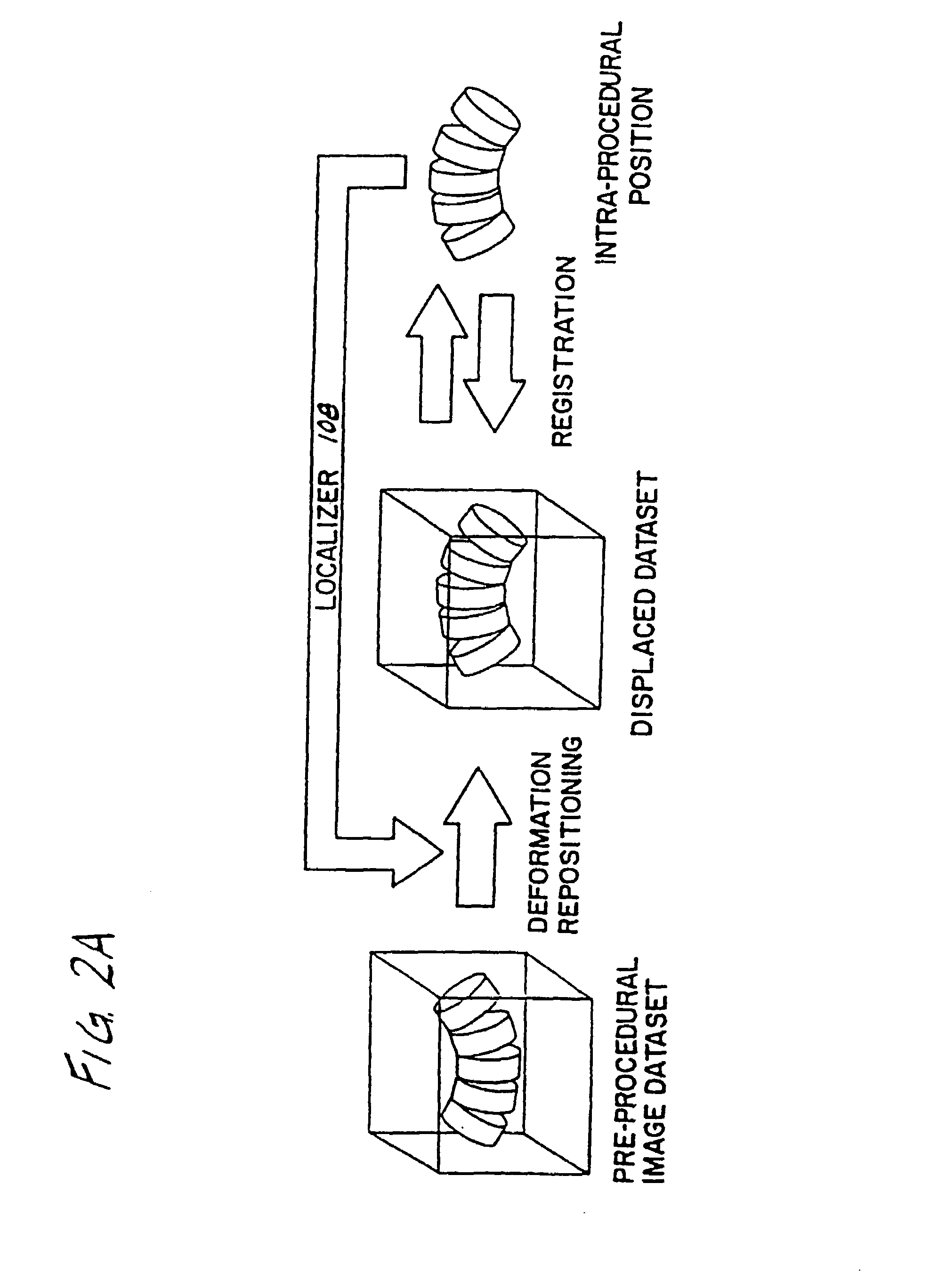
[0078]Referring to FIGS. 2A and 2B, an overview of operation of one preferred embodiment of the system according to the invention is illustrated. Prior to a particular procedure, the body elements which will be part of the procedure are scanned to determine their alignment, i.e., their pre-operative position. For example, the alignment may be such as illustrated in FIG. 3 wherein body elements 10, 20, and 30 are more or less aligned in parallel. These body elements may be bones or other rigid bodies. In FIG. 3, three-dimensional skeletal elements 10, 20, 30 are depicted in two dimensions as highly stylized vertebral bodies, with square vertebra 11, 21, 31, small rectangular pedicles 12, 22, 32, and triangular spinous processes 13, 23, 33. During imaging, scans are taken at intervals through the body parts 10, 20, 30 as represented in FIG. 3 by nine straight lines generally referred to be reference character 40. At least one scan must be obtained through each of the body elements and...
PUM
Abstract
A system for use during a medical or surgical procedure on a body. The system generates an image representing the position of one or more body elements during the procedure using scans generated by a scanner prior or during the procedure. The image data set has reference points for each of the body elements, the reference points of a particular body element having a fixed spatial relation to the particular body element. The system includes an apparatus for identifying, during the procedure, the relative position of each of the reference points of each of the body elements to be displayed. The system also includes a processor for modifying the image data set according to the identified relative position of each of the reference points during the procedure, as identified by the identifying apparatus, said processor generating a displaced image data set representing the position of the body elements during the procedure. The system also includes a display utilizing the displaced image data set generated by the processor, illustrating the relative position of the body elements during the procedure. Methods relating to the system are also disclosed. Also disclosed are devices for use with a surgical navigation system having a sensor array which is in communication with the device to identify its position. The device may be a reference frame for attachment of a body part of the patient, such as a cranial reference arc frame for attachment to the head or a spine reference arc frame for attachment to the spine. The device may also be a localization frame for positioning an instrument relative to a body part, such as a localization biopsy guide frame for positioning a biopsy needle, a localization drill guide assembly for positioning a drill bit, a localization drill yoke assembly for positioning a drill, or a ventriculostomy probe for positioning a catheter.
Description
CROSS REFERENCE TO RELATED APPLICATIONS[0001]This application is a divisional of application Ser. No. 09 / 105,068, filed Jun. 26, 1998, now abandoned, which is a divisional of Ser. No. 08 / 809,404, filed Mar. 21, 1997, which issued as U.S. Pat. No. 6,236,875, which is a 371 of PCT / US95 / 12894, filed Oct. 5, 1995, which claims priority to Ser. No. 60 / 003,415, filed Sep. 8, 1995, now abandoned, and is a continuation Ser. No. 08 / 319,615, filed Oct. 7, 1994, now abandoned, which is a continuation-in-part of Ser. No. 08 / 053,076, filed Apr. 26, 1993, now abandoned.BACKGROUND OF THE INVENTION[0002]The invention relates generally to systems which use and generate images during medical and surgical procedures, which images assist in executing the procedures and indicate the relative position of various body parts and instruments. In particular, the invention relates to a system for generating images during medical and surgical procedures based on a scan taken prior to or during the procedure an...
Claims
Application Information
Patent Timeline
Application Date:The date an application was filed.
Publication Date:The date a patent or application was officially published.
First Publication Date:The earliest publication date of a patent with the same application number.
Issue Date:Publication date of the patent grant document.
PCT Entry Date:The Entry date of PCT National Phase.
Estimated Expiry Date:The statutory expiry date of a patent right according to the Patent Law, and it is the longest term of protection that the patent right can achieve without the termination of the patent right due to other reasons(Term extension factor has been taken into account ).
Invalid Date:Actual expiry date is based on effective date or publication date of legal transaction data of invalid patent.