Method of fabricating composite tooling using closed-loop direct-metal deposition

a technology of composite tooling and closed-loop deposition, applied in the direction of other manufacturing equipment/tools, nuclear engineering, railway components, etc., to achieve the effect of low cos

Inactive Publication Date: 2006-11-21
MAZUMDER JYOTI +1
View PDF38 Cites 38 Cited by
  • Summary
  • Abstract
  • Description
  • Claims
  • Application Information

AI Technical Summary

Benefits of technology

[0007]The deposited material is preferably an alloy chosen to maximize the performance service life of the tooling. This can be achieved by combining ductile face centered cubic materials with relatively brittle non-cubic faces to achieve adequate toughness during service and reasonable wear resistance.
[0008]The selection of metals for use in the alloy is important for promoting certain phases as well as protection against chemical degradation. For example, molybdenum has very little solubility in aluminum. Forming the deposited section with metallurgically bonded molybdenum alloys in the formation of a casting die for use with aluminum will improve the service life by maintaining the surface integrity. The deposition process parameters control the pool cooling rate which controls the phase transformation kinetics. Therefore, the deposition process parameters may be varied to promote the generation of desired phases. The high cooling rate and strong convection associated with laser melting and solidification promotes atom trapping leading to extension of the solid solutions and these non-equilibrium syntheses may be utilized to dissolve low solubility materials such as yttrium and hafnium, in order to optimize the composite metallurgy.

Problems solved by technology

The large and heavy tooling components create problems in the use of DMD processes since their high mass may make accurate translation difficult, and if the deposition must be formed on a curved surface difficulty is achieved in positioning the part relative to the laser feed.

Method used


Image

  • Method of fabricating composite tooling using closed-loop direct-metal deposition
  • Method of fabricating composite tooling using closed-loop direct-metal deposition
  • Method of fabricating composite tooling using closed-loop direct-metal deposition

Examples


Embodiment Construction

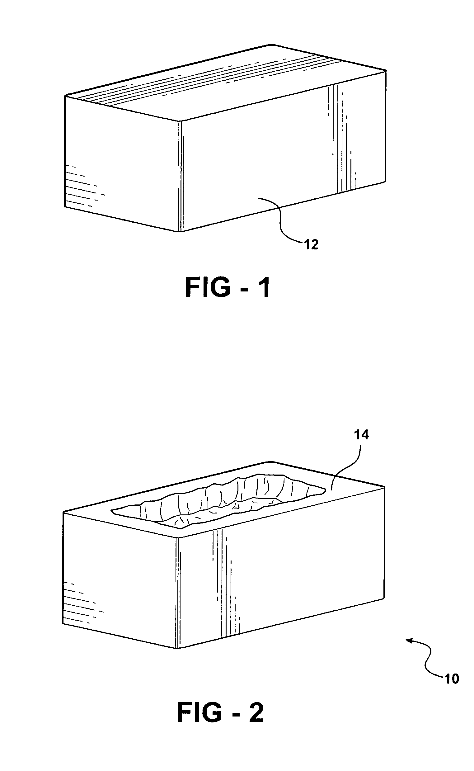
[0015]FIG. 2 represents a female stamping die generally indicated at 10 which may be formed by the method of the present invention. It should be understood that the method is applicable to formation of a wide variety of tooling in addition to stamping dies such as trim steels, flange steels, die inserts and the like.

[0016]The completed die 10 is formed beginning with the base 12 as illustrated in FIG. 1. The base, adapted to be supported within a stamping press, does not include the work engaging surfaces of the die and accordingly it is not subject to the same wear as the working surfaces when in use. It can generally be formed of a less wear-resistant, more ductile material and lower cost than the work-engaging surfaces of the die. For example, it might be formed as a casting from a relatively low strength steel.

[0017]Work-engaging surfaces 14 of the die 10 are formed on the upper surface of the base 12 of an alloy which is harder and more wear-resistant than the metal of the base...


PUM

PropertyMeasurementUnit
solubilityaaaaaaaaaa
ductilityaaaaaaaaaa
volumeaaaaaaaaaa

Abstract

Manufacturing tools having a base and a working surface, such as trim steels, flange steels and die inserts, are formed by fabricating or casting a substrate out of a relatively ductile, low wear-resistant metal and forming the working surfaces such as cutting edges, flanging surfaces, die surfaces and die inserts by depositing layers of relatively hard, wear-resistant materials to the substrate by closed-loop direct-metal deposition or laser cladding. A multi-axis numerically controlled robot may be used to position and move a beam and deposition material over large substrates in forming such tooling.

Description

RELATED APPLICATION[0001]This application claims priority of U.S. Provisional Patent Application Ser. No. 60 / 407,016 filed Aug. 29, 2002, which is incorporated herein by reference.FIELD OF THE INVENTION[0002]This invention relates to a method of fabricating manufacturing tooling such as stamping dies, trim steels, die inserts and the like which involves forming a base of a first metal having relatively high ductility and low cost and forming the work-engaging areas on the space by depositing sections of a second metal using closed-loop direct-metal deposition.BACKGROUND OF THE INVENTION[0003]Currently, a variety of forms of manufacturing tooling such as stamping dies, trim steels, flange steels and die inserts are formed from homogeneous, high cost, alloy tool steels, either from wrought or cast materials. The materials used are often determined by the properties of the working or cutting edges or die surfaces while the larger volume of the tooling merely supports these working surf...

Claims


Application Information

Patent Timeline
Patent Type & Authority Patents(United States)
IPC IPC(8): G06F19/00B22F3/105B23K26/34B23K31/02
CPCB22F3/1055B23K26/34B23K31/025B23K26/3206B23K26/3226B22F2005/002B22F2998/00B23K2203/10B22F7/04B23K26/32B23K2103/08B23K2103/10B23K2103/18B23K2103/50Y02P10/25B22F10/38B22F10/25B22F12/90
Inventor MAZUMDER, JYOTIDIPIETRO, FRANK A.
Owner MAZUMDER JYOTI
Why Eureka
Try Eureka