Stacking-type, multi-flow, heat exchangers and methods for manufacturing such heat exchangers

a technology of heat exchangers and manufacturing methods, applied in indirect heat exchangers, laminated elements, lighting and heating apparatus, etc., can solve the problems of reducing the productivity of the manufacturing method, difficult to accurately position the inner fins within the predetermined cavities, and increasing the time for assembling, so as to reduce the manufacturing time of the heat exchanger. , the effect of increasing the productivity of the heat exchanger manufacturing method and facilitating the positioning of the inner fins

Inactive Publication Date: 2006-11-28
SANDEN CORP
View PDF33 Cites 10 Cited by
  • Summary
  • Abstract
  • Description
  • Claims
  • Application Information

AI Technical Summary

Benefits of technology

[0016]Accordingly, a need has arisen to provide a method for manufacturing stacking-type, multi-flow, heat exchangers, which reduces the manufacturing time for a heat transfer tube, thereby increasing the productivity of the heat exchanger manufacturing method, which facilitates the positioning of inner fins being disposed at predetermined positions in each tube plate, and which prevents a positional shift of the inner fins after the inner fins are so positioned, and to provide stacking-type, multi-flow, heat exchangers, which are manufactured by using this manufacturing method.
[0018]In this method, it is preferred that the stacked pair of tube plates are temporarily secured simultaneously with the cutting at the above-described cutting step. As a result, the manufacturing method may be further simplified.
[0019]Further, it is preferred that at least one end portion of each heat transfer tube in a width direction of the heat transfer tube is formed as a shape linearly extending in an outward or lateral direction. In such a structure, the nipping or seizing of the inner-fin forming material between the pair of tube plates may be facilitated, and the cutting of the inner-fin forming material and the end portions of the pair of tube plates simultaneously also may be facilitated.
[0023]In the method for manufacturing a stacking-type, multi-flow, heat exchanger, according to the present invention, the time required for manufacturing heat transfer tubes may be reduced significantly, and by reducing the manufacturing time, the productivity of the method for manufacturing the heat exchanger may be increased significantly. Moreover, the positioning of inner fins at the predetermined positions on a tube plate may be facilitated and may be carried out with a high degree of accuracy. Further, a positional shift of an inner fin at the time of manufacturing a heat transfer tube may be prevented readily.
[0024]Therefore, a stacking-type, multi-flow, heat exchanger, manufactured by using this method, may be produced at a high productivity and at a low cost. In addition, a heat exchanger, having a high degree of reliability in the positional accuracy of inner fins and other components and having a high quality, may be provided.

Problems solved by technology

(1) As the number of heat transfer tubes used per heat exchanger increases, the time for assemble increases, and the productivity declines.
(2) It is difficult to accurately position inner fins within the predetermined cavities of the fluid passage forming portions of a tube plate during of the above-described S13.
(3) A positional shift of an inner fin may occur during the covering of first-tube plate 101 with second tube plate 101′ at above-described S15.

Method used


Image

  • Stacking-type, multi-flow, heat exchangers and methods for manufacturing such heat exchangers
  • Stacking-type, multi-flow, heat exchangers and methods for manufacturing such heat exchangers
  • Stacking-type, multi-flow, heat exchangers and methods for manufacturing such heat exchangers

Examples


first embodiment

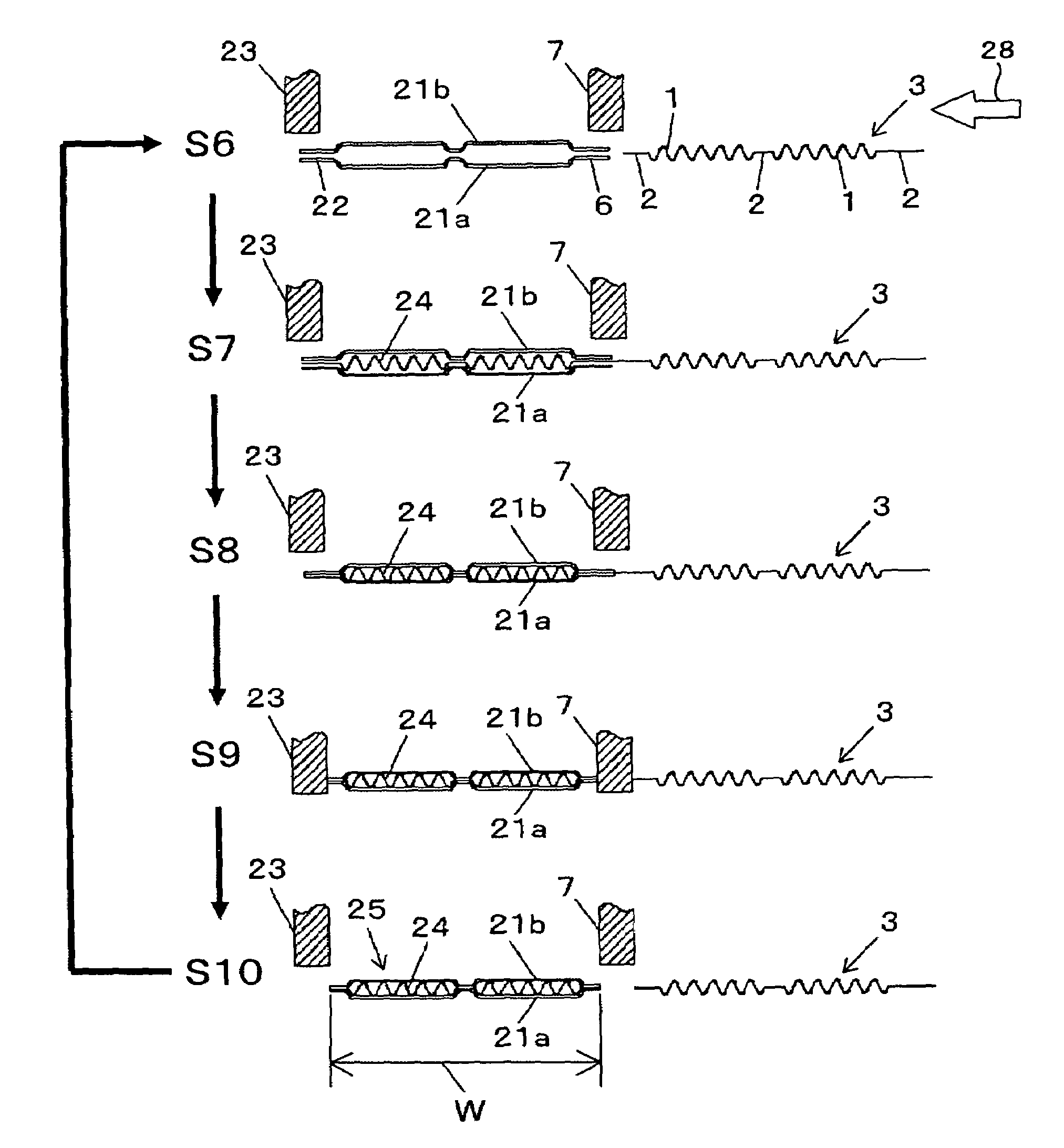
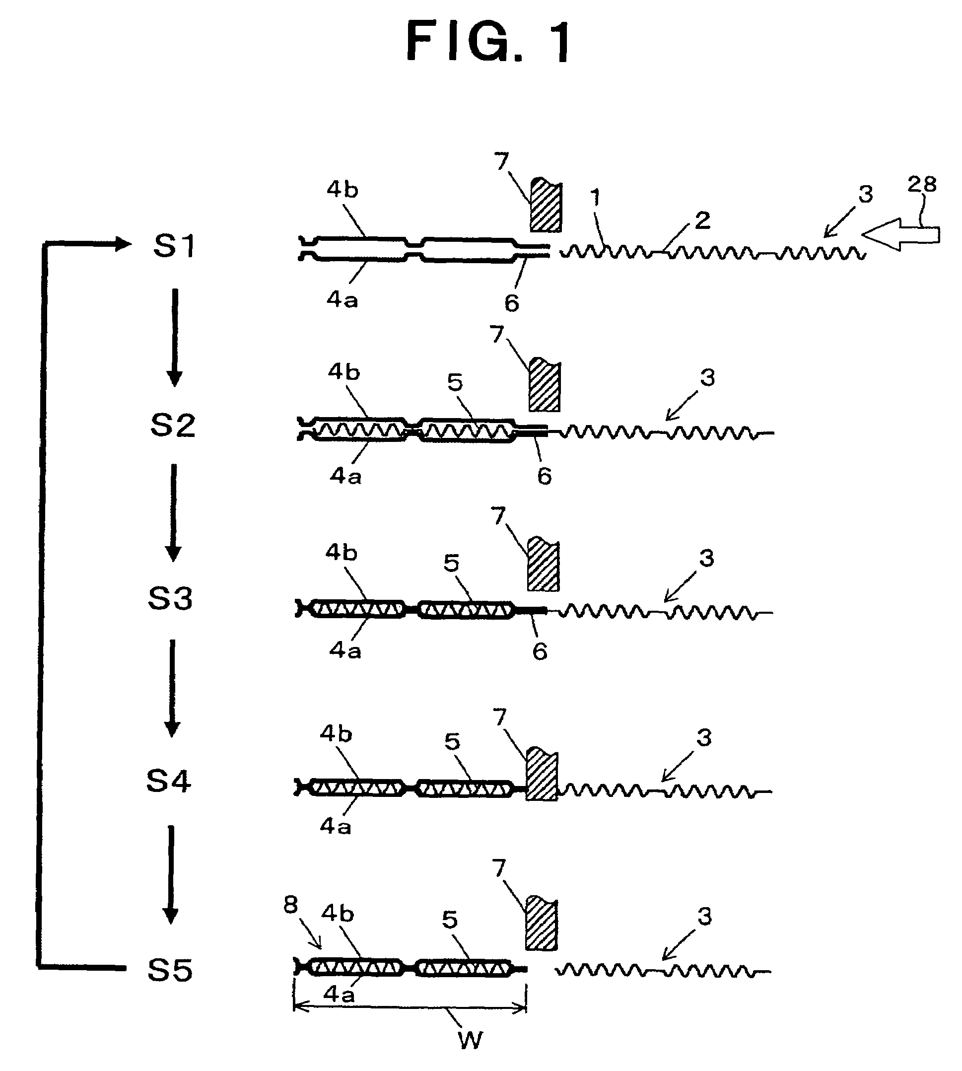
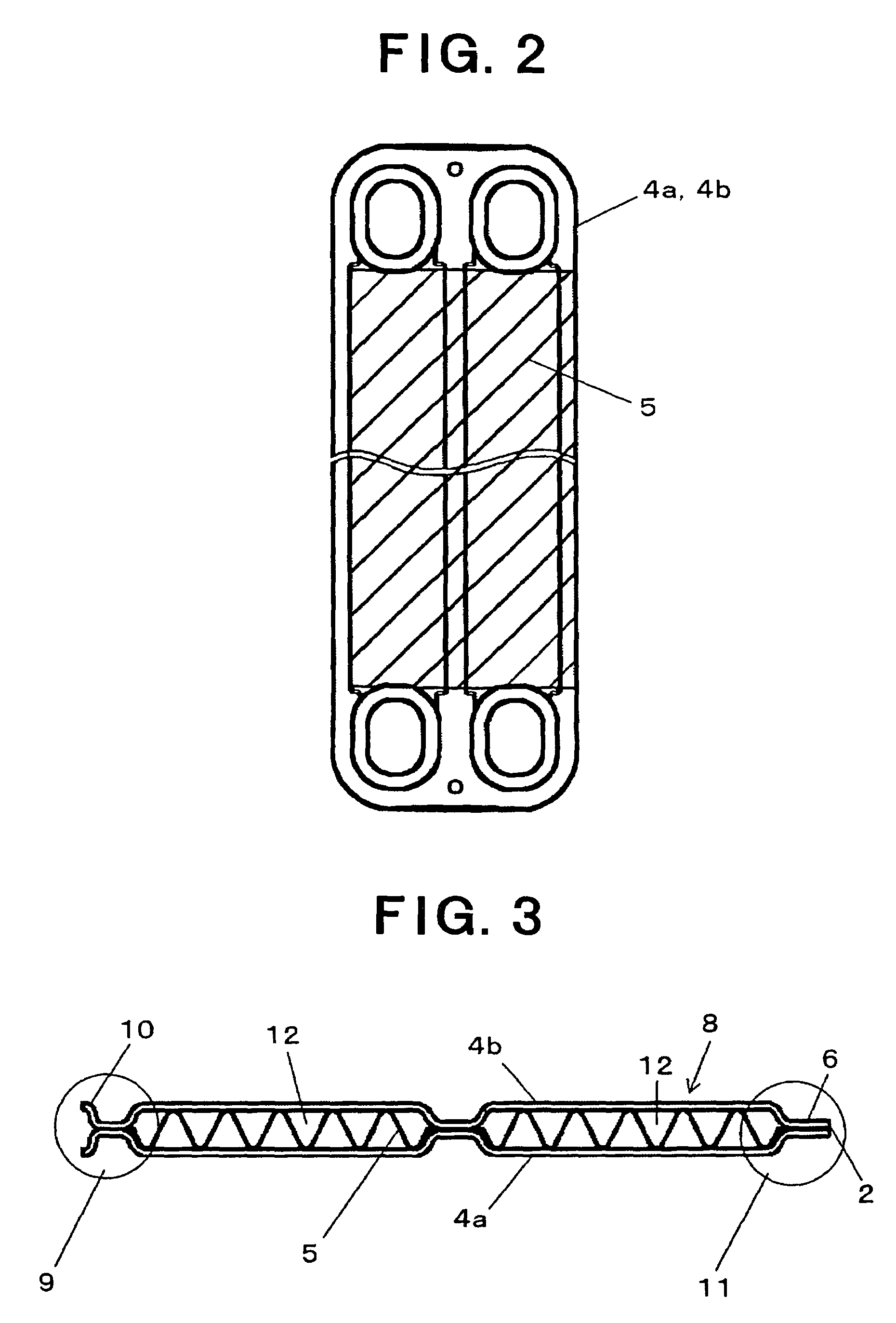
[0041]Referring to FIGS. 1–3, a method for manufacturing a stacking-type, multi-flow, heat exchanger is depicted according to the present invention. FIG. 1 depicts steps of a process for manufacturing a heat transfer tube, FIG. 2 depicts a relationship between a tube plate and an inner fin used in the method, as depicted in FIG. 1, and FIG. 3 depicts a heat transfer tube manufactured by the method.

[0042]The manufacturing method, as depicted in FIG. 1, comprises the following steps:

[0043]Step 1 (S1): An inner fin formed as a wave shape is not cut beforehand, and it is formed as a continuous, inner-fin forming material 3. Inner-fin forming material 3 is formed as a continuous material extending in a width direction W of a heat transfer tube to be formed, and wavy or undulating portions 1 and linear portions 2 are arranged alternately in continuous material 3 in width direction W of the heat transfer tube. A pair of tube plates 4a and 4b, which may be formed by pressing, are disposed s...

second embodiment

[0062]In the above-described second embodiment, the time required for manufacturing heat transfer tubes 25 may be reduced significantly, and the productivity of methods for manufacturing a stacking-type, multi-flow, heat exchanger may be increased significantly. Further, because an inner fin is inserted between tube plates 21a and 21b as a continuous inner-fin forming material 3, the positioning of the inner fin may be facilitated significantly, and the positioning accuracy may be increased significantly. In particular, because the linear portions of inner-fin forming material 3 are nipped or seized at both sides in the width direction W of heat transfer tubes 25, the positioning of inner fin 24 may be achieved with more certainty. Moreover, tube plates 21a and 21b may be temporarily and simultaneously secured by cutting the end portions of the tube plates and the inner-fin forming material. Consequently, a positional shift of an inner fin, which may occur in known processes, may be...


PUM

PropertyMeasurementUnit
widthaaaaaaaaaa
structureaaaaaaaaaa
shapeaaaaaaaaaa

Abstract

In a method for manufacturing a stacking-type, multi-flow, heat exchanger, heat transfer tubes and outer fins are stacked alternately, each heat transfer tube being formed by connecting a pair of tube plates and including an inner fin therebetween. The manufacturing method includes the steps of disposing the tube plates so as to oppose each other, inserting an inner-fin forming material between the tube plates, stacking the tube plates with respect to each other so as to nip or seize the inner-fin forming material between the tube plates, and cutting the inner-fin forming material and end portions of the tube plates simultaneously. By this method, the time for required manufacturing heat transfer tubes may be reduced significantly, and the productivity of the heat exchanger may be increased significantly. The positioning of inner fins may be achieved with a high degree of accuracy. Therefore, a stacking-type, multi-flow, heat exchanger having superior performance qualities and manufactured with a high degree of reliability may be manufactured at a reduced cost.

Description

BACKGROUND OF THE INVENTION[0001]1. Field of the Invention[0002]The present invention relates to a stacking-type, multi-flow, heat exchangers, each heat exchanger comprising a plurality of heat transfer tubes, each tube having an inner fin therein and outer fins which are stacked alternately between the tubes, and methods for manufacturing such heat exchangers. Specifically, the present invention relates to a process for manufacturing the heat transfer tubes, each tube having an inner fin therein, and a stacking-type, multi-flow, heat exchanger manufactured by using the methods, suitable as a heat exchanger for use in an air conditioning system, in particular, for vehicles.[0003]2. Description of Related Art[0004]Stacking-type, multi-flow, heat exchangers having alternately stacked heat transfer tubes, each tube having an inner fin therein and outer fins therebetween, are known, for example, as depicted in FIGS. 10–12. In a heat exchanger, thus constructed, a heat transfer tube is f...

Claims


Application Information

Patent Timeline
Patent Type & Authority Patents(United States)
IPC IPC(8): B21D53/04F28F3/06B21D53/08F28D1/03F28F3/02F28F3/08
CPCF28D1/0333F28F3/025Y10T29/49366Y10T29/49384F28F2265/32
Inventor OHNO, TAKAYUKICHIBA, TOMOHIROKAZARI, KENGO
Owner SANDEN CORP
Why Eureka
Try Eureka