Hydraulic control and operation system for a railroad car retarder

a technology of hydraulic control and operating system, which is applied in the direction of braking system, separation process, filtration separation, etc., can solve the problems of excess pressure excursions or pressure spikes that can propagate back through the hydraulic system and damage system components, and achieve the effect of preventing operating pressure spikes

Inactive Publication Date: 2006-11-28
PRECISION RAIL & MFG
View PDF24 Cites 9 Cited by
  • Summary
  • Abstract
  • Description
  • Claims
  • Application Information

AI Technical Summary

Benefits of technology

[0007]In accordance with the present invention, an improved hydraulic control and operating system for a railroad car retarder addresses all of the prior art operating problems with a comprehensive monitoring, control and operating format for a retarder of the type that utilizes a double-acting hydraulic cylinder supplied with operating oil from a motor-driven hydraulic pump. The pump draws operating oil from a reservoir and delivers the oil to one end of the hydraulic cylinder via an appropriate hydraulic control valve. The system includes means for preventing operating pressure spikes and excess pressure excursions from propagating back to system components that would be damaged, heat exchange means for controlling the temperature of the operating oil below a specified maximum operating temperature, means for filtering the operating oil in both the oil supply and return lines, and means for operating the retarder from either a central freight yard control center or at the location of the retarder itself.

Problems solved by technology

Shock loads on a hydraulic retarder operating system are regularly encountered and may result in pressure spikes or excess pressure excursions that can propagate back through the hydraulic system and damage system components.

Method used


Image

  • Hydraulic control and operation system for a railroad car retarder
  • Hydraulic control and operation system for a railroad car retarder
  • Hydraulic control and operation system for a railroad car retarder

Examples


Embodiment Construction

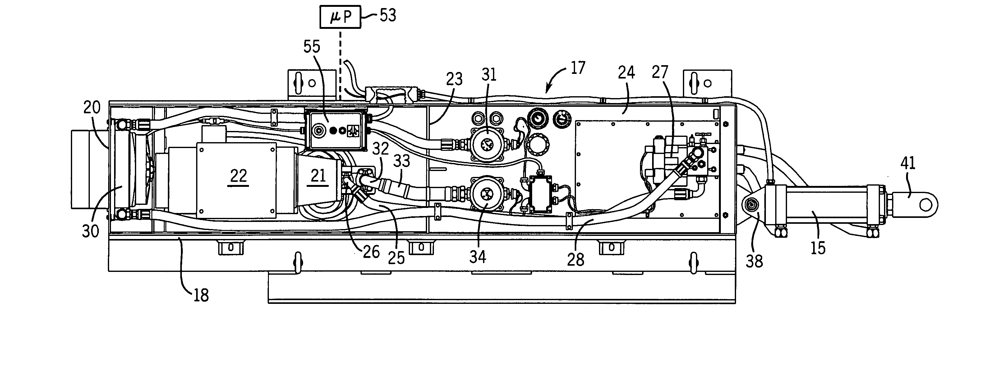
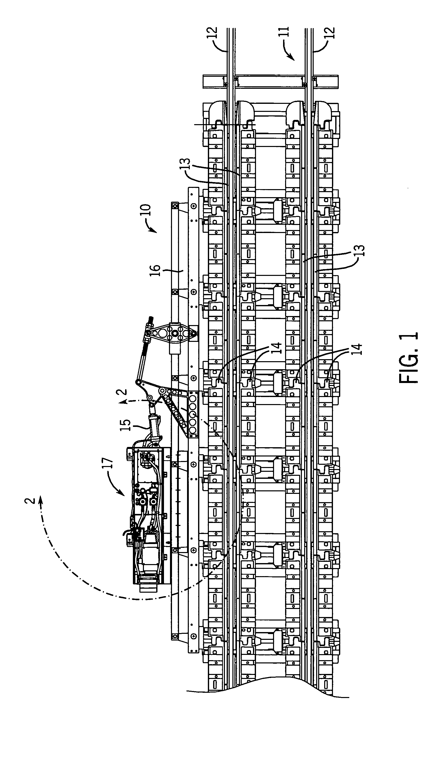
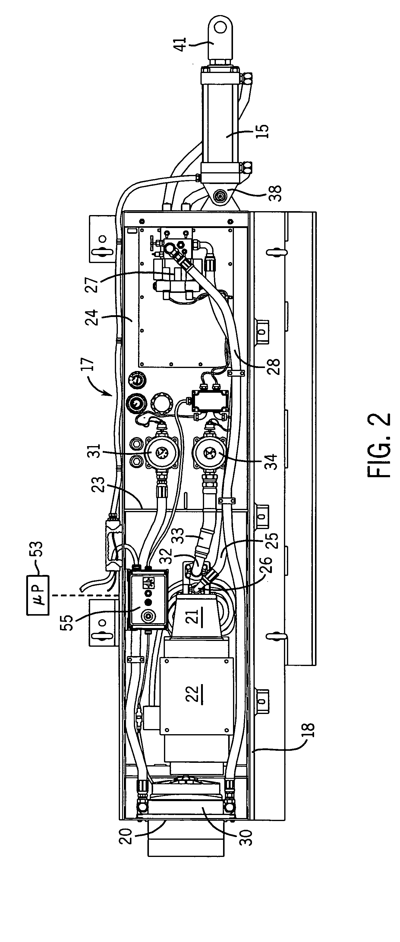
[0022]In FIG. 1, a railroad car retarder 10 is shown mounted along a section of track 11 comprising a pair of conventional rails 12. It will be understood that the track 11 continues in both directions from the retarder with railcars entering the retarder from the right in the direction shown by the arrow. Each retarder 10 includes a pair of parallel braking bars 13 positioned on opposite sides of and parallel to each of the rails 12. The braking bars 13 are also positioned above the tops of the rails 12 such that, when moved toward one another, the braking bars engage the sides of the car wheels to effect a braking or retarding of the moving rail car, all in a manner well known in the art.

[0023]In the conventional retarder shown in FIG. 1, the braking bars 13 are biased to open (to move away from one another and from the rail car wheels) by sets of bias springs 14 positioned along the length of the retarder. A hydraulic cylinder 15 is operatively connected to a parallel bar linkage...


PUM

PropertyMeasurementUnit
timeaaaaaaaaaa
pressureaaaaaaaaaa
pressureaaaaaaaaaa

Abstract

A hydraulic control and operating system is provided for a railroad car retarder to control the movement of railroad cars in railroad classification yard. The system utilizes a double-acting hydraulic cylinder to operate the retarder mechanism and includes a hydraulic control circuit that provides protection against pressure spikes and high pressure excursions, high and low temperature excursions, low oil levels and oil filter fouling. The above system not only shuts itself down to prevent damage, but provides a warning to maintenance staff that service should be performed long before a need for system shut-down is required. The system includes a central operating panel in the rail yard control center, remote control panel located at the position of the retarder and the system can be connected for operation from a completely remote location.

Description

CROSS-REFERENCE TO RELATED APPLICATIONS[0001]This application is based on and claims the benefit of Provisional Application No. 60 / 484,216, filed Jul. 1, 2003.FIELD OF THE INVENTION[0002]The present invention pertains to a hydraulic control and operating system for a railroad car retarder and, more particularly, to such a control and operating system that includes protection against hydraulic shock and overload, protection against operational problems at extreme temperatures, and the ability to monitor and operate retarder function on-site and from a remote location in addition to normal operation from a railroad yard tower.[0003]A railroad car retarder is used in a railroad classification yard to regulate the speed of freight cars being arranged to make up a train or temporarily sidetracked. Many types of hydraulic, pneumatic and mechanical retarders are known in the industry, but in all cases, such retarders must operate effectively and efficiently in adverse weather and in climat...

Claims


Application Information

Patent Timeline
Patent Type & Authority Patents(United States)
IPC IPC(8): B60T8/18B60T7/18F02D13/04
CPCB60T7/18
Inventor BRAATZ, JAMES D.ZIESE, LOWELL B.BOHME, RICHARD
Owner PRECISION RAIL & MFG
Why Eureka
Try Eureka