Method for fusion splicing optical fibers and fusion splicer

a technology of which is applied in the field of fusion splicing optical fibers and fusion splicers, can solve the problems of uniform self-alignment value of optical fibers, difficult to set intentional offset to compensate for self-alignment value, and worker ignorance of optical fiber typ

Active Publication Date: 2006-11-28
SUMITOMO ELECTRIC IND LTD
View PDF10 Cites 20 Cited by
  • Summary
  • Abstract
  • Description
  • Claims
  • Application Information

AI Technical Summary

Benefits of technology

[0008]An object of the present invention is to provide a method and an apparatus that allow optical fibers to be fusion spliced so that the connected portion has a small loss or a prescribed loss.

Problems solved by technology

Optical fibers tend to melt more by heat when additives such as fluorine are added in the cladding material and, for this reason, the self-alignment value of optical fibers is not uniform and depends on the type of optical fiber.
In addition, due to the surrounding environment such as the temperature of the surroundings or wind present during the fusion splicing, it is not always the case that there is a constant relationship between the heating power and the melted state of the optical fiber.
In addition, there are many cases where a worker does not know the type of optical fibers to be spliced or whether there is core decentering.
Consequently, as the number of types of optical fibers used increases, which is recently the case, it becomes difficult to set the intentional offset that will compensate for the self-alignment value.

Method used


Image

  • Method for fusion splicing optical fibers and fusion splicer
  • Method for fusion splicing optical fibers and fusion splicer
  • Method for fusion splicing optical fibers and fusion splicer

Examples


Embodiment Construction

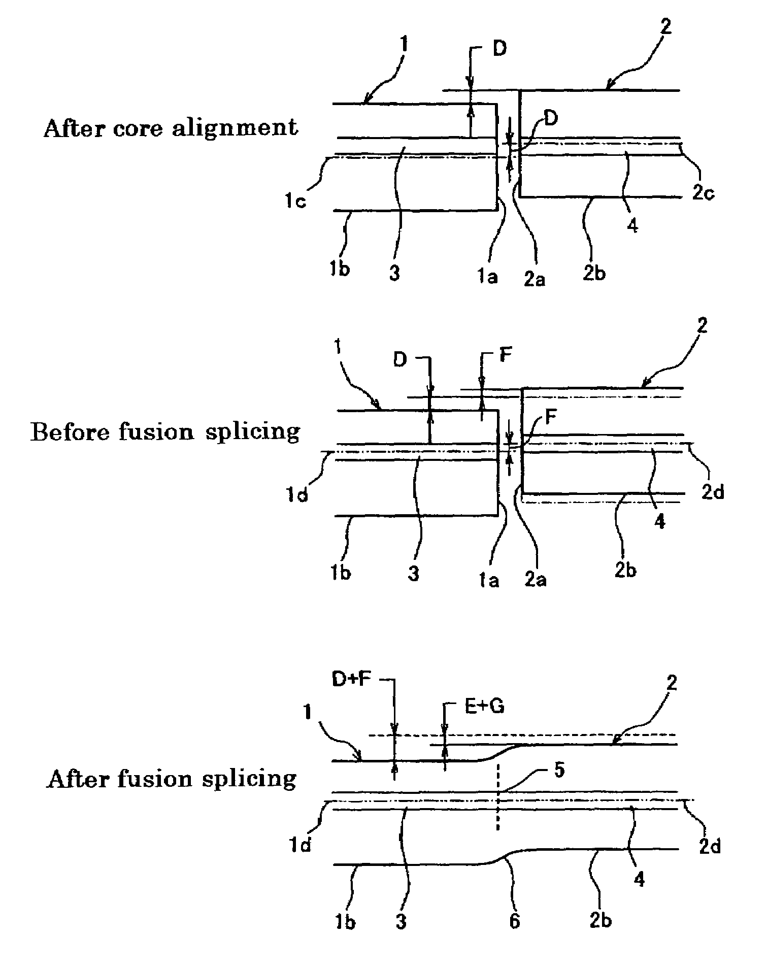
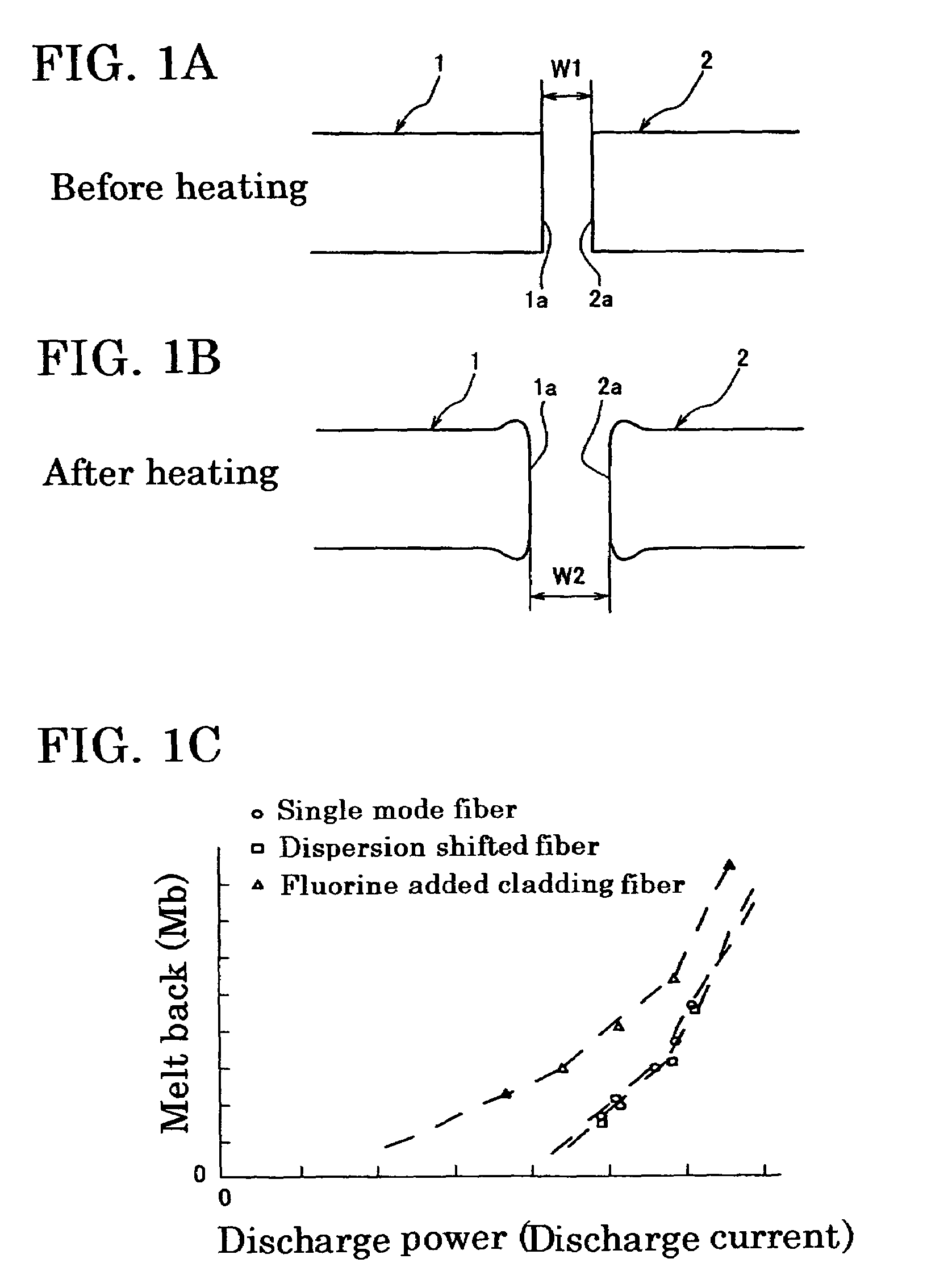
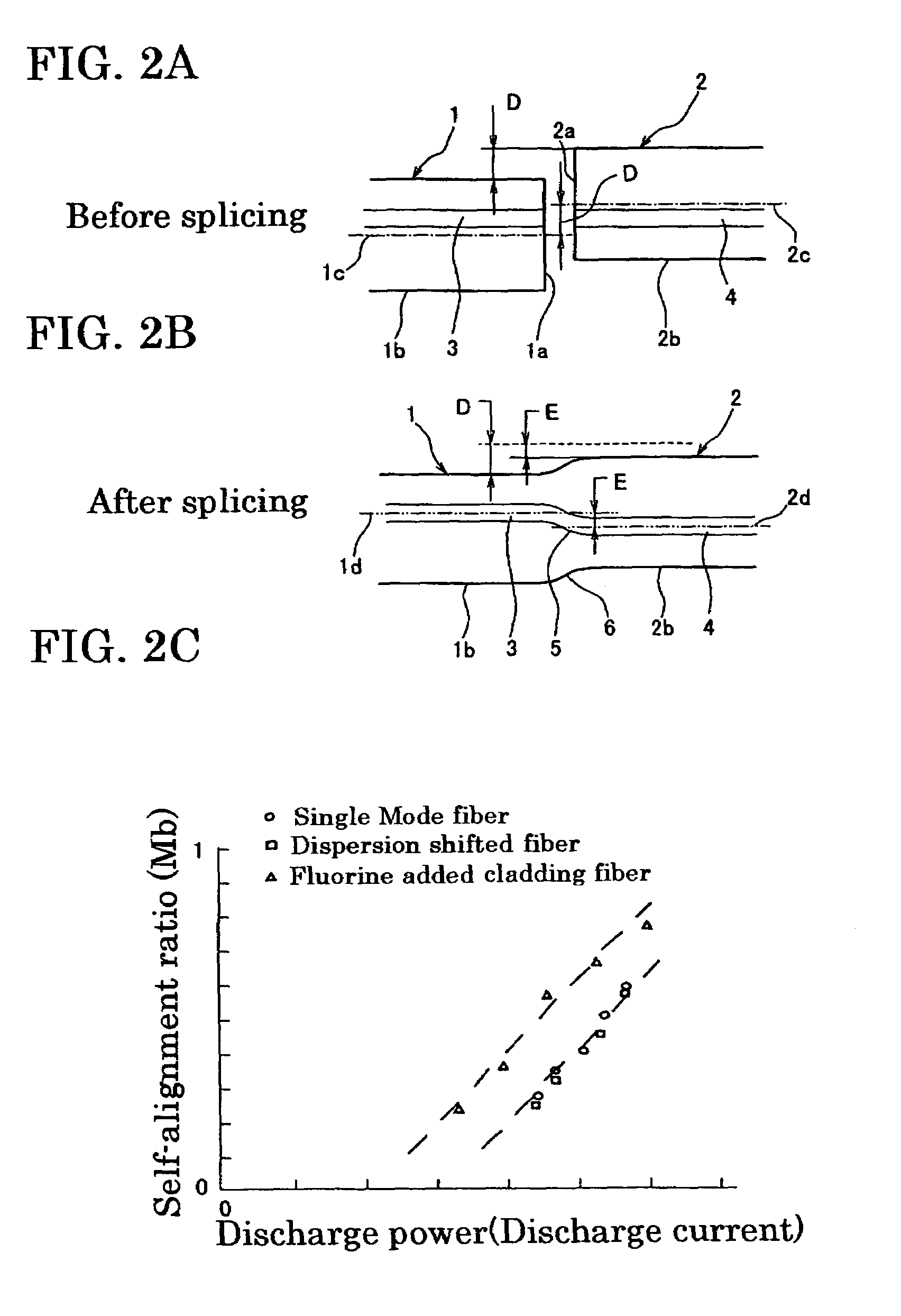
[0022]In performing the offset compensation of optical fibers to be fusion spliced, it is necessary to know the melting characteristics of the optical fiber. The melting characteristics include the relationship between melted condition value (e.g., melt back) of an optical fiber optical fiber and discharge power, and the relationship between self-alignment ratio of an optical fiber and discharge power. By obtaining these relations in advance of fusion splicing, it is possible to carry out axial offset compensation appropriately, allowing fusion splicing to be performed with a prescribed splicing loss.

[0023]FIGS. 1A and 1B are schematic diagrams describing melt back, where FIG. 1A shows the condition before test discharge, and FIG. 2B shows the condition after test discharge. In FIG. 1A, the first optical fiber 1 and second optical fiber 2 are in an abutting arrangement, with a gap W1 provided between the splicing ends 1a and 2a. When test discharge is carried out, the splicing ends ...


PUM

PropertyMeasurementUnit
surface tensionaaaaaaaaaa
discharge currentaaaaaaaaaa
timeaaaaaaaaaa

Abstract

A method and apparatus capable of fusion splicing optical fibers to have a low loss or a prescribed loss. The method includes (a) detecting fiber positions and core positions of optical fibers to be spliced at an abutting position and a fiber offset that is caused when said optical fibers are in core alignment (b) determining the self-alignment ratio corresponding to the preferred melted condition value based on a predetermined expression for a relationship between melted condition value and self-alignment ratio, (c1) determining an intentional offset that achieves a prescribed splicing loss based on the fiber offset and the self-alignment ratio, (d1) aligning the core positions by offsetting the intentional offset value, and (e1) heating and fusing the optical fibers.

Description

BACKGROUND OF THE INVENTION[0001]1. Field of the Invention[0002]The present invention relates to a method for abutting and fusion splicing the splicing ends of optical fibers and an apparatus used in the method.[0003]2. Description of the Background Art[0004]When splicing ends of two optical fibers that are to be spliced to each other are melted, melting is usually brought about after aligning so that the respective core positions of the two optical fibers correspond. Alignment that is carried out in order to align the core positions is referred to in this specification as “core alignment”. When the core center and the fiber center do not correspond (when the core is decenterd), splicing will be performed in a state in which the positions of the two fibers are offset (condition in which the shapes of the fibers are offset) even though the positions of the two optical fiber cores are aligned to each other. In this case, the two optical fibers move so that the offset in the shapes is ...

Claims


Application Information

Patent Timeline
Patent Type & Authority Patents(United States)
IPC IPC(8): G02B6/255C03B37/15
CPCG02B6/2551
Inventor TAKAYANAGI, HIROSHIHATTORI, KAZUNARI
Owner SUMITOMO ELECTRIC IND LTD
Why Eureka
Try Eureka