Combine harvester

Inactive Publication Date: 2006-11-28
CLAAS SELBSTFAHRENDE ERNTEMASCHINEN GMBH
View PDF30 Cites 10 Cited by
  • Summary
  • Abstract
  • Description
  • Claims
  • Application Information

AI Technical Summary

Benefits of technology

[0007]It is the object of the present invention to arrange a separation unit as known from prior art in a self-propell

Problems solved by technology

Due to the fact that for a proper function of such a separation unit the longitudinal axis of the rotor housing, and the separation rotor needs to be erected by an angle of more than 30 degrees from its front end to its discharge end, such a separation unit is difficult to integrate into the known concepts of self-propelled rotary combines.
If the separation unit disclosed in the cited reference should be adapted into such a combine respectively, the harvested material needs to be distributed from the bottom into the rotor housing, which usually makes additional feeding elements necessary, and due to the fact that the lower feeding zone is already arranged approximately in the second third of the total height of the combine harvest

Method used


Image

  • Combine harvester
  • Combine harvester
  • Combine harvester

Examples


Embodiment Construction

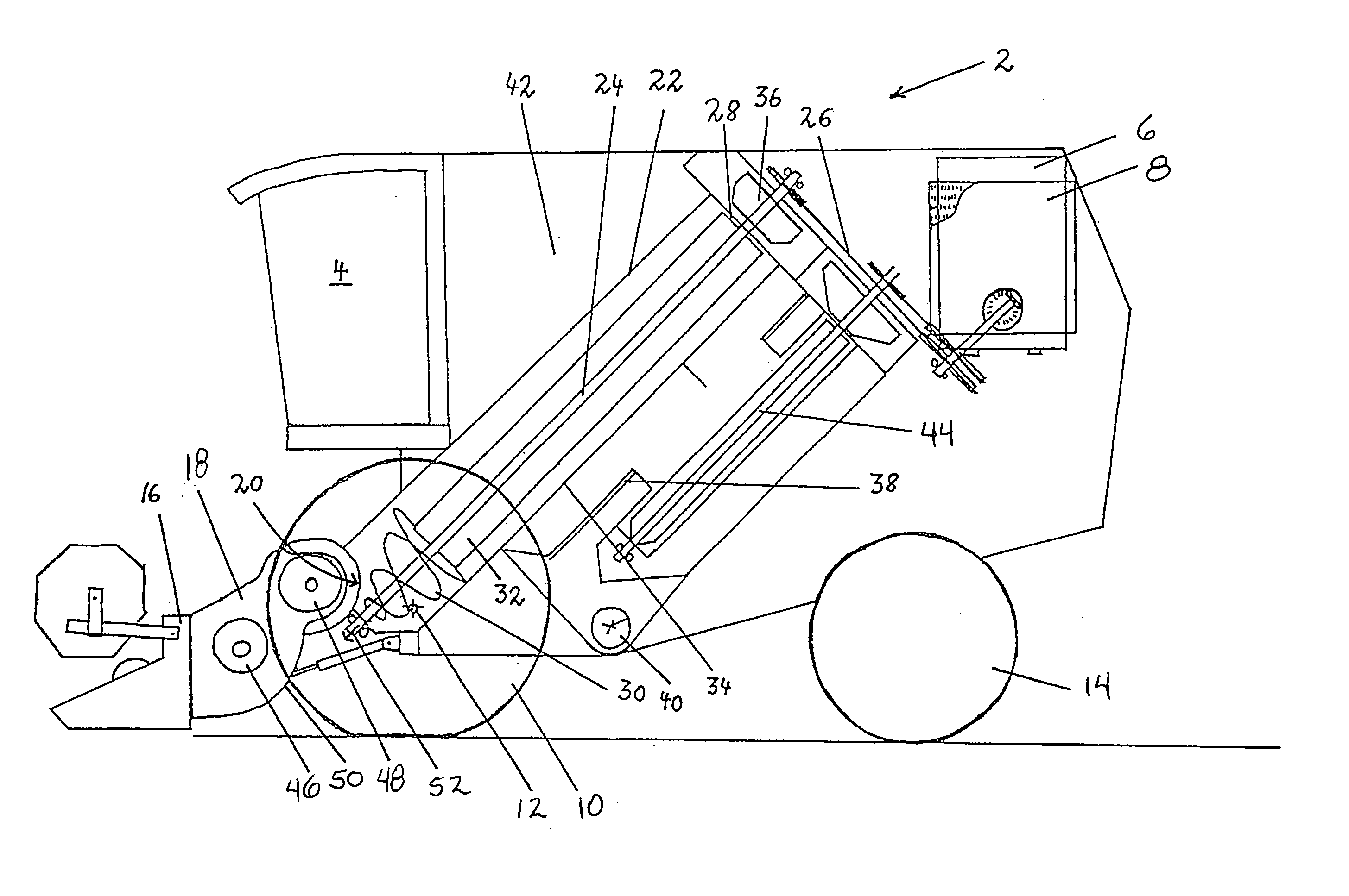
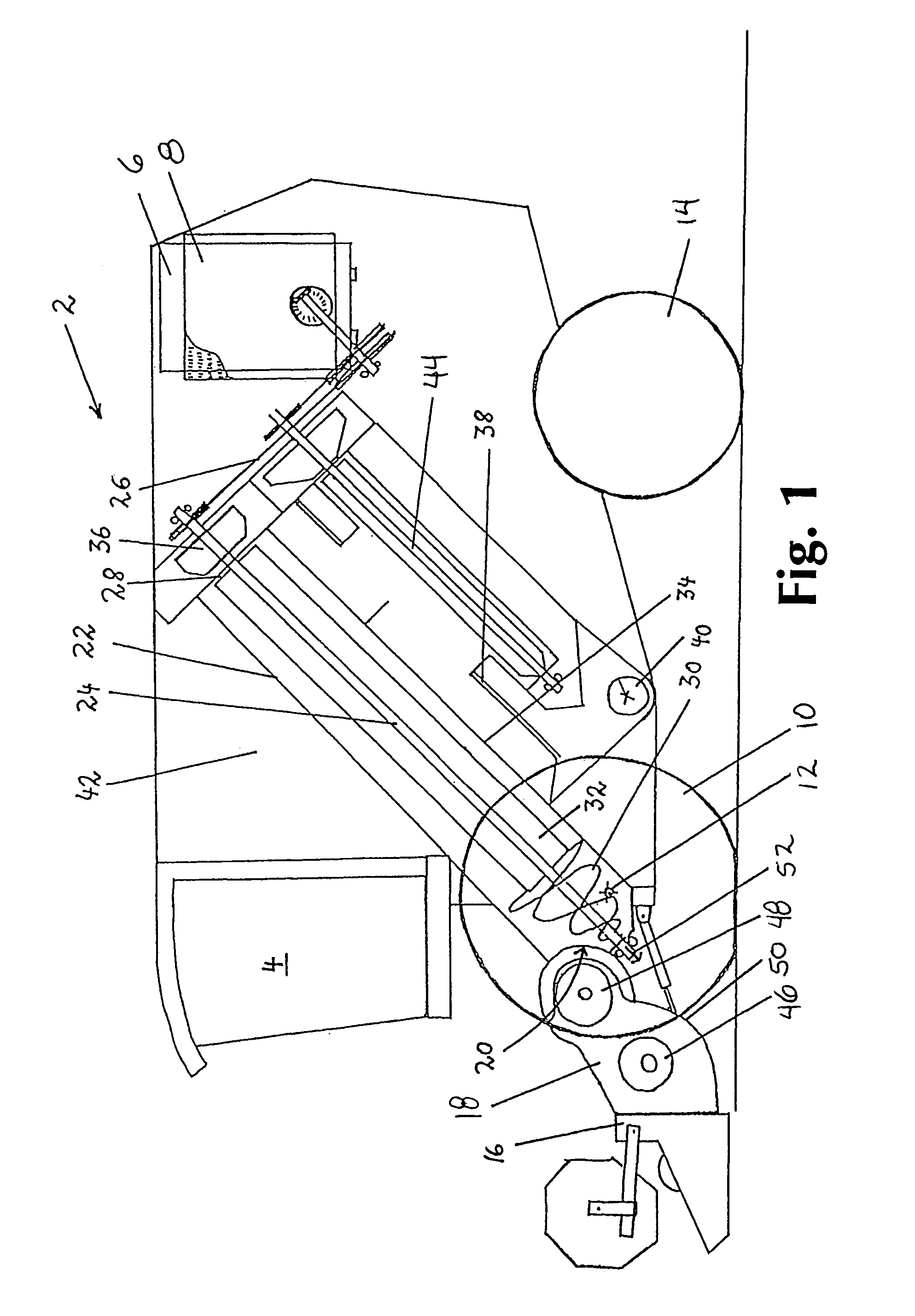
[0016]A combine harvester 2 shown in FIG. 1 is equipped with a driver's cabin 4, an engine 6 with a cooling system 8, a front wheel 10 with a rotational axis 12, a rear wheel 14, a cutterbar 16, and a feeder house 18, which distributes the harvested material from the cutterbar 16 into the feeding opening 20 of the rotor housing 22. Inside of the rotor housing 22 there is arranged a separation rotor 24 which is rotatably driven by driving elements 26, here shown as pulley drives, from the power of engine 6. Seen along the rotational axis of the separation rotor 24 from the feeding opening 20 towards the dis-charge end 28 of the rotor housing 22, the front section of the separation rotor 24 comprises auger blades 30 which approximately define the length of the feeding zone where the harvested material is fed into the rotor housing 22. The middle and rearward section of the separation rotor 24 is equipped with beater plates 32 which approximately define the length of the separation zon...


PUM


Abstract

A combine harvester with a rotor housing which is positioned in a lengthwise direction and with an inclined angle towards the horizontal line inside of the combine. To arrange the rotor housing in a favorable way inside of the combine harvester, it is suggested to use a feeder house which comprises elements which distribute harvested material from the cutterbar in an up and rearward direction towards its discharge end, said discharge end being arranged in a height substantially above of the rotational axis of the front wheels and in a region before the rotational axis of the front wheels, the discharge end feeds the harvested material into the feeding opening of the rotor housing of the separation unit being arranged in the upper half of it, whereby the rotor housing reaches with its front from a region before the rotational axis of the front wheels and a lower third of the height of the combine harvester to its rear being arranged in the top rear half portion of the combine harvester.

Description

CROSS REFERENCE TO RELATED APPLICATIONS[0001]This application claims priority of PCT Application No. PCT / EP02 / 00682 filed 24 Jan. 2002 and which named the United States as a designated country. PCT Application PCT / EP02 / 00682 was published on 26 Sep. 2002 as Publication No. WO 02 / 074062 A1 and claims priority of prior Foreign Application No. 0106730.5 filed in Great Britain on 19 Mar. 2001.TECHNICAL FIELD OF THE INVENTION[0002]The present invention relates to a combine harvester with a separation unit comprising a rotary driven separation rotor arranged in a rotor housing with a feeding zone where harvested material is fed into the rotor housing, a separation zone with sieve means arranged in the rotor housing, of said separation zone, a discharge zone which is located at the discharge end of the rotor housing and a sucking blower unit which sucks an air flow stream at least through the sieve means into the separation zone and the discharge zone, and a grain collecting element arrang...

Claims


Application Information

Patent Timeline
IPC IPC(8): A01F7/06A01D41/02A01F12/44
CPCA01D41/02A01F12/442
Inventor VISAGIE, ANDRIEBARRELMEYER, THOMAS
Owner CLAAS SELBSTFAHRENDE ERNTEMASCHINEN GMBH
Why Eureka
Try Eureka