Regenerable adsorption system

a sorbent and adsorption technology, applied in the direction of chemistry apparatus and processes, separation processes, dispersed particle separation, etc., can solve the problems of significant negative impact of humidity on the performance of zeolite sorbents, and achieve the effects of reducing power requirements, significant weight and volume savings, and net energy savings

Active Publication Date: 2006-11-28
PRECISION COMBUSTION
View PDF12 Cites 39 Cited by
  • Summary
  • Abstract
  • Description
  • Claims
  • Application Information

AI Technical Summary

Benefits of technology

[0009]The present invention provides an energy efficient, lightweight sorption system for removal of environmental contaminants in space flight applications. More particularly, the present invention provides an alternative technology for removing both CO2 and trace contaminants within a single unit employing a sorption bed comprising ultra-short-channel-length metal meshes coated with zeolite sorbents. The metal meshes further define a means for direct, resistive electrical-heating thereby providing the potential for short regeneration times, reduced power requirement, and net energy savings in comparison to the conventional system. The present invention eliminates the need for a separate trace contaminant control unit resulting in an opportunity for significant weight and volume savings.
[0010]It has now been found that zeolites deposited on ultra-short-channel-length metal mesh elements, known as Microlith® and commercially available from Precision Combustion, Inc., located in North Haven, Conn., effectively adsorb a number of the contaminants of interest. The inert Microlith® ultra-short-channel-length metal mesh substrate and the use of a binder during deposition of the zeolites on the mesh substrate results in volumetric sorbent loadings considerably lower than if the adsorbents were used as a packed bed (e.g., the carbon bed currently employed). However, the ability to directly resistively heat the metal mesh support provides for relatively rapid periodic regenerations. Therefore, the weight and volume of the current TCCS may be substantially reduced (by as much as 75 wt %) by use of zeolites supported on Microlith® ultra-short-channel-length metal mesh elements in conjunction with periodic sorbent regeneration.
[0011]Since cabin air is fed directly to the TCCS, humidity may have a significant negative impact on the performance of the zeolite sorbents. Drying agents are used to mitigate the effect of humidity on sorbent effectiveness and precede the current carbon dioxide removal assembly (“CDRA”). In one embodiment of the present invention, a Microlith® ultra-short-channel-length metal mesh based TCCS is combined with the CDRA function. The system incorporates the existing desiccant beds located upstream of the current pellet-based CDRA bed. These driers mitigate the negative impact of humidity on the effectiveness of 5A for CO2 sorption. Locating the Microlith® ultra-short-channel-length metal mesh based TCCS system behind the CO2 removal bed provides a dry stream to the zeolites used for trace contaminant removal.
[0012]In another embodiment of the present invention, the packed bed for CO2 removal was replaced with a Microlith® ultra-short-channel-length metal mesh supported 5A zeolite sorbent. As with the TCCS, the Microlith® ultra-short-channel-length metal mesh provided considerably lower volumetric sorbent loadings than the 5A pellet bed (approximately 30%). However, resistive heating of the Microlith® ultra-short-channel-length metal mesh support permits faster periodic regenerations. In yet another embodiment of the present invention, successful integration of both the CDRA and TCCS systems based entirely on Microlith® ultra-short-channel-length metal mesh supported sorbents—and similar in size to the current CDRA unit alone—eliminates the current TCCS unit entirely with corresponding weight and volume savings. Depending upon the design and regeneration requirements, the integrated system offers power savings, as well as additional weight savings, versus the current CDRA pellet bed. The current TCCS and CDRA system is illustrated in FIG. 1A and the integrated Microlith® ultra-short-channel-length metal mesh based CDRA / TCCS system is illustrated in FIG. 1B.

Problems solved by technology

Since cabin air is fed directly to the TCCS, humidity may have a significant negative impact on the performance of the zeolite sorbents.

Method used


Image

  • Regenerable adsorption system
  • Regenerable adsorption system
  • Regenerable adsorption system

Examples


Embodiment Construction

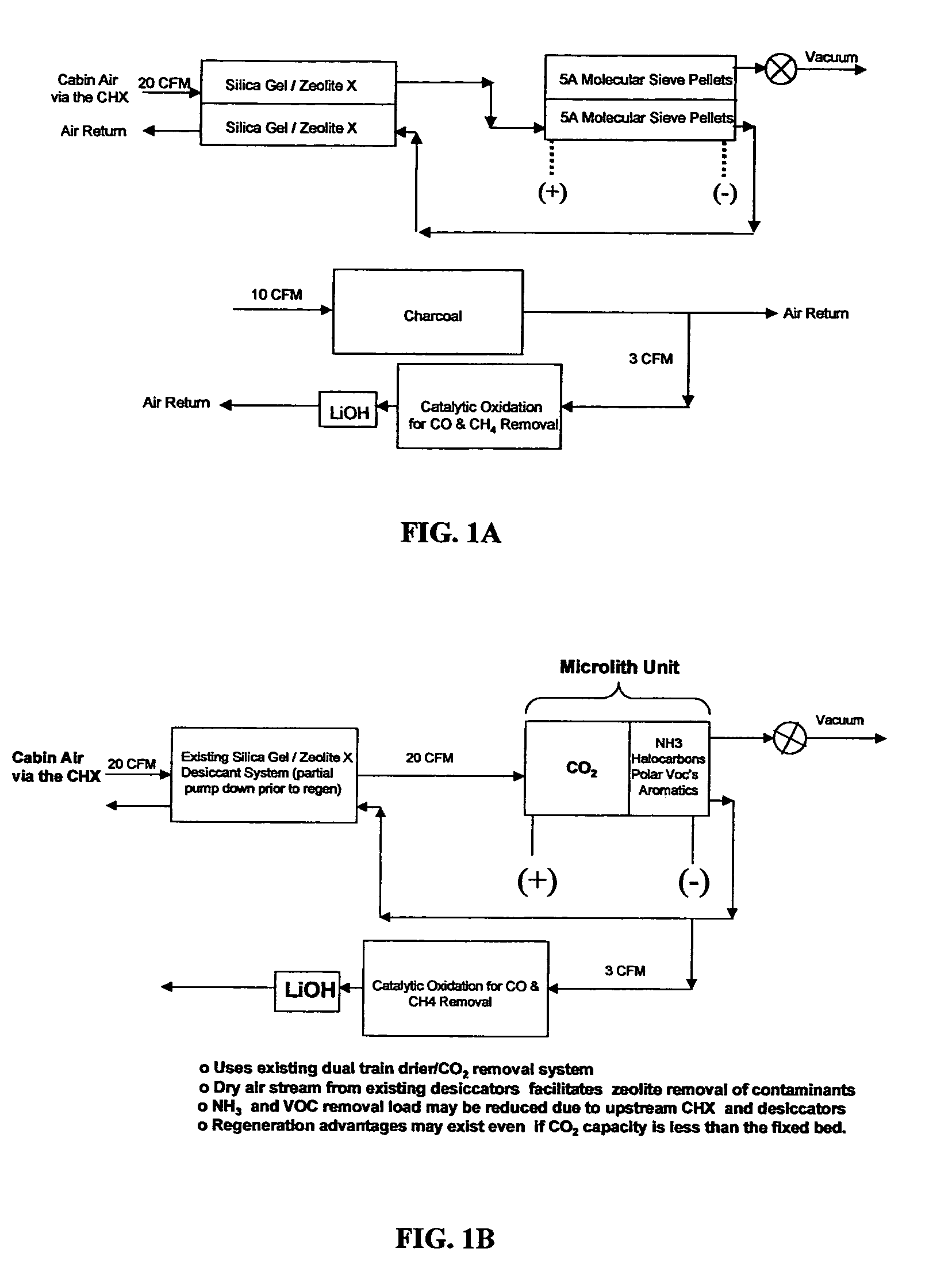
[0022]FIG. 1A provides a diagram of the system currently employed on the ISS. The dehumidification and CO2 adsorption beds operate in swing mode. A separate charcoal bed for adsorption of TCCS also is shown. FIG. 1B provides a diagram of an embodiment of the present invention. The charcoal bed is eliminated and replaced with a regenerable CO2 and TCCS adsorption bed which also may operate in swing mode.

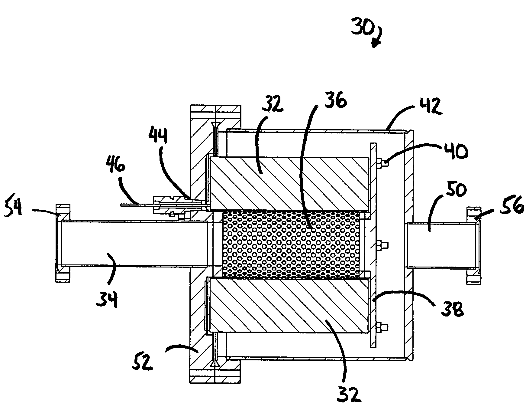
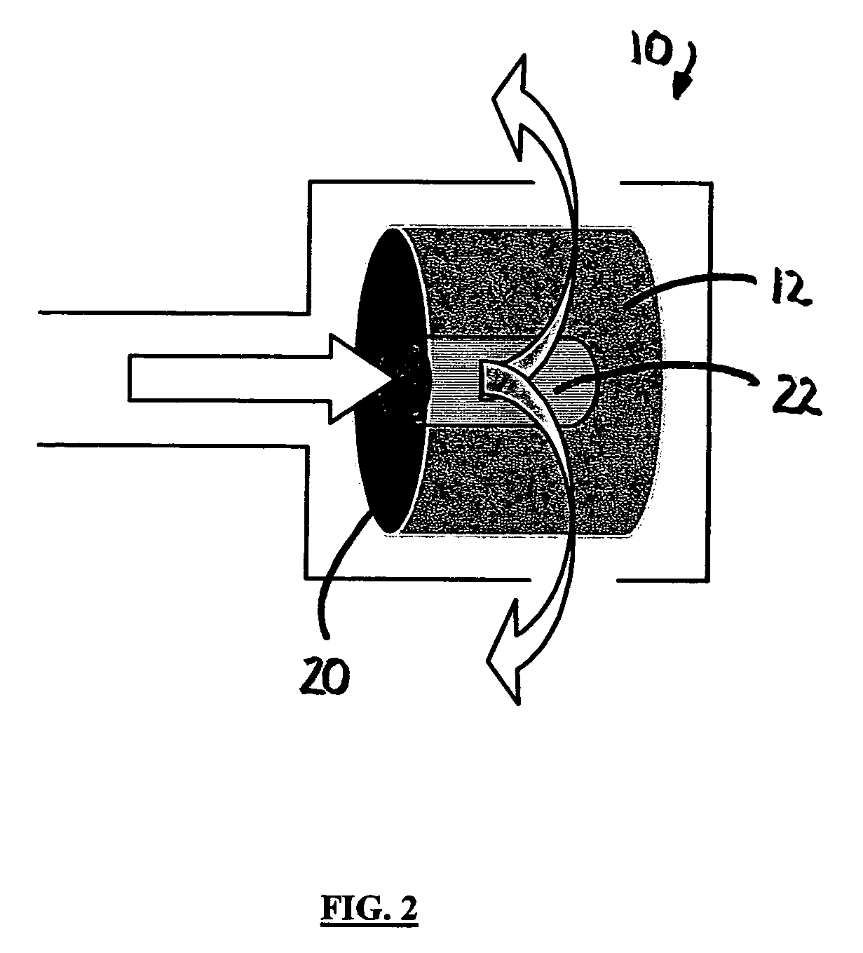
[0023]One preferred embodiment of the present invention, as shown in FIG. 2, comprises an axial flow coiled sorber substrate configuration 10, commonly referred to as a “jelly-roll”configuration, defined by a coiled Microlith® ultra-short-channel-length metal mesh 12. Unlike its axial flow counterpart, bypassing of the flowstream around the sorber substrate is not a concern in the radial flow configuration. In addition, the radial flow arrangement provides volumetric sorbent loadings at least comparable to a linear bank of screen elements. Furthermore, from the electrical and hardware...


PUM

PropertyMeasurementUnit
thicknessaaaaaaaaaa
diameteraaaaaaaaaa
lengthaaaaaaaaaa

Abstract

A method for regenerable adsorption includes providing a substrate that defines at least one layer of ultra short channel length mesh capable of conducting an electrical current therethrough, coating at least a portion of the substrate with a desired sorbent for trace contaminant control or CO2 sorption, resistively heating the substrate, and passing a flowstream through the substrate and in contact with the sorbent.

Description

CROSS-REFERENCE[0001]This application claims the benefit of U.S. Provisional Application No. 60 / 569,714 filed May 10, 2004.GOVERNMENT RIGHTS[0002]This invention was made with government support under NASA Contract No. NAS8-02108. The U.S. government holds certain rights in this invention.FIELD OF THE INVENTION[0003]The present invention is generally directed to a method and apparatus for removing trace contaminants from a flowstream. In particular, this invention provides an improved adsorption process for spacecraft cabin air quality control. More particularly, this invention provides for an energy efficient, lightweight sorption system for the removal of environmental contaminants in space flight applications.BACKGROUND OF THE INVENTION[0004]Adsorption methods for removing trace contaminants from a flowstream typically comprise passing the flowstream over or through a sorbent structure. The sorbent structure may be defined by a plurality of pellets or an array of tubes or plates o...

Claims


Application Information

Patent Timeline
Patent Type & Authority Patents(United States)
IPC IPC(8): B01D53/04
CPCB01D53/0431B01D53/0454B01D53/32B01J20/183B01J20/28033B01J20/3441B01D2253/102B01D2253/108B01D2253/302B01D2257/406B01D2257/504B01D2257/70B01D2259/40096B01D2259/41B01D2259/4575Y02C10/08Y02C20/40
Inventor ROYCHOUDHURY, SUBIRPERRY, JAYWALSH, DENNIS
Owner PRECISION COMBUSTION
Why Eureka
Try Eureka