
Use of liquid junction potentials for electrophoresis without applied voltage in a microfluidic channel

a microfluidic channel and electrophoresis technology, applied in flow mixers, electrolysis, diaphragms, etc., can solve the problems of microfluidic devices, microfluidic electrophoresis adds complexity to the design, and significant problems in many microfluidic systems

Inactive Publication Date: 2006-11-28
WASHINGTON THE UNIV OF
View PDF2 Cites 29 Cited by
  • Summary
  • Abstract
  • Description
  • Claims
  • Application Information

AI Technical Summary

Benefits of technology

"The present invention provides a liquid junction potential (LJP) device and methods for controlling the movement of charged particles in microfluidic devices without the need for an external electrical potential. The LJP can be used in microfluidic devices for particle transport control, including focusing, acceleration, and deceleration, as well as concentration of reactants and the mixing of fluids. The invention also provides microfluidic devices incorporating the LJP and methods of making them. The technical effects of the invention include improved control over particle movement and separation in microfluidic devices, as well as the ability to extract particles from a fluid."

Problems solved by technology

While effective, microfluidic electrophoresis adds complexity to the design of a microfluidic device by requiring additional fabrication techniques and steps for the incorporation of metal electrodes into the microfluidic channel.
Although its effects often go overlooked (Demas, J. N., et al., Appl Spectrosc 1998, 52, 755–762; Greenlee, R. D., et al., Biotechnol Prog 1998,14, 300–309), the LJP could cause significant problems in many microfluidic systems by inducing spurious electrophoretic transport of analytes.
Beyond this application, the LJP has not to date been exploited as a tool due to its relatively low magnitude and the short distances over which it acts.

Method used


Image

  • Use of liquid junction potentials for electrophoresis without applied voltage in a microfluidic channel
  • Use of liquid junction potentials for electrophoresis without applied voltage in a microfluidic channel
  • Use of liquid junction potentials for electrophoresis without applied voltage in a microfluidic channel

Examples


control example 1

Free Diffusion

[0215]Experiment 1 (conditions shown in Table 1) served as a control for the rest of the experiments; it represents the case where no LJP was formed because the ionic compositions of the fluid pairs were balanced. In this case it was expected and observed that diffusion was the only mechanism of transverse mass transport. The results from the diffusion experiment are shown in FIG. 9. Addition of either 1 M NaCl or 1 M Na2SO4 to both streams produced results that were indistinguishable from the control.

[0216]As the residence time increased, the extent of interdiffusion increased, as expected; slope of the concentration profile at the midline of the channel are less steep. It is interesting to note that at the midline, the concentration rapidly reached the equilibrium concentration, and then remained fixed. Thus, the concentration profiles appeared to ‘pivot’ about this point with increasing residence time. These results are in good agreement with other experiments that ...

example 2

Accelerating Mass Transport Using LJP

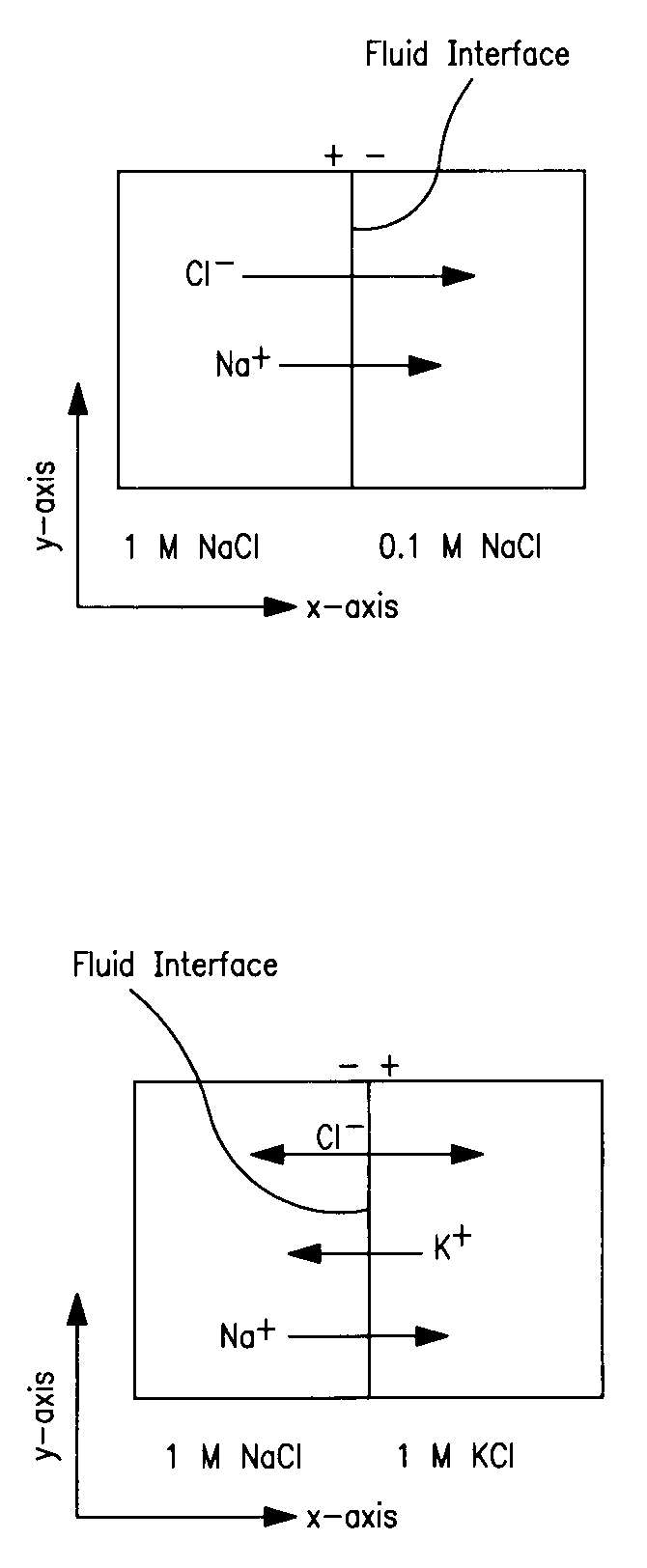
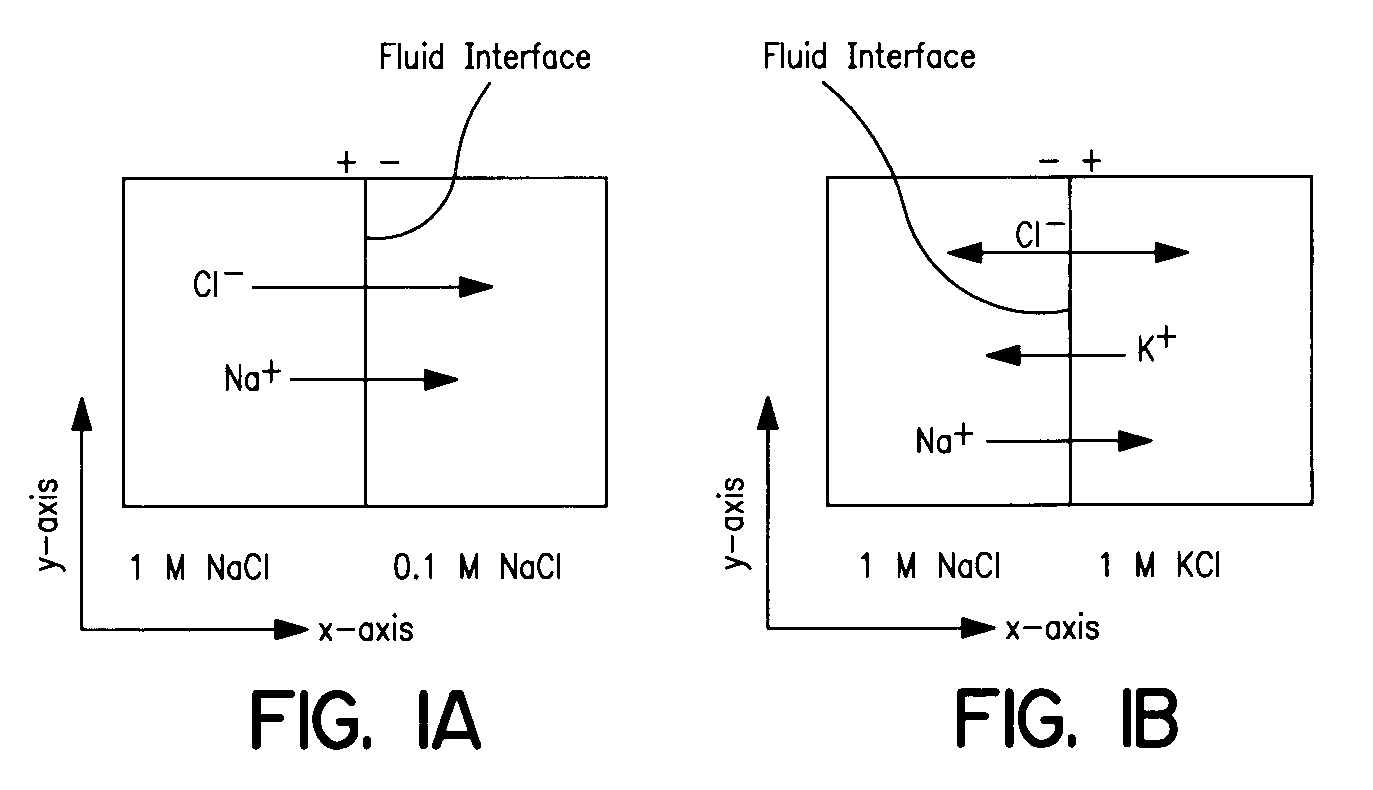
[0217]In Experiment 2, the unlabeled solution contained a high concentration of NaCl and the labeled solution contained no NaCl. It was expected that this would generate a LJP because the diffusivity of Na+ (1.33×10⁻⁵ cm2 / sec) is 45% slower than that of Cl− (2.03×10⁻⁵ cm2 / sec) (Lide, D. R., CRC Handbook of Chemistry and Physics, 75th ed.; CRC Press, Cleveland, Ohio, 1995). Based on the model prediction of the field (FIG. 10) and potential (FIG. 11), we expected that negatively-charged fluorescein would experience an electrophoretic force acting in the same direction as the diffusive transport, thereby accelerating its net flux across the midline. The resulting concentration profiles from this experiment are shown in FIG. 12, which show a depletion of the fluorescein in a region of the labeled solution near the interface; there was a ‘dip’ in the normalized intensity profile. This dip is caused by the electrophoretic migration of dye near the inte...

example 3

Decelerating Mass Transport Using LJP

[0219]In Experiment 3, the unlabeled solution contained a high concentration of Na2SO4 and the labeled solution contained none. A LJP was predicted in this case because Na+ (1.33×10⁻⁵ cm2 / sec) diffuses 23% faster than SO4−2 (1.03×10⁻⁵ cm2 / sec) (Lide, D. R., CRC Handbook of Chemistry and Physics, 75th ed.; CRC Press, Cleveland, Ohio:, 1995). In this experiment the anionic species diffused faster than the cationic species, which was the opposite of Experiment 2. Therefore, the sign of the electric field generated in this case was anticipated to be opposite to that of the Experiment 2. In this case we expected that the fluorescein transport across the channel would be decelerated by the LJP, resulting in a concentration of the fluorescein in its solution of origin. The experimental concentration profiles are shown in FIG. 14. These concentration profiles show that there was electrophoretic transport of the tracer molecule in the opposite direction o...


PUM

PropertyMeasurementUnit
residence timeaaaaaaaaaa
molecular weightaaaaaaaaaa
length scaleaaaaaaaaaa

Abstract

This invention provides methods for using liquid junction potentials to control the transport of charged particles in fluid streams that are in laminar flow within microfluidic channels. Applications of the methods of this invention include sample preconditioning (removal of interfering substances), electrophoretic separation (fractionation) of charged particles, enhanced or delayed mixing of charged particles across a fluid interface relative to diffusion only, focusing charged particles in a fluid stream in one or two dimensions, and concentration of charged reactants at a fluid interface.

Description

CROSS REFERENCE TO RELATED APPLICATIONS[0001]This application claims priority to U.S. provisional application Ser. No. 60 / 328,328 filed Oct. 9, 2001, which is hereby incorporated by reference in its entirety to the extent not inconsistent with the disclosure herewith.SOURCES OF GOVERNMENT FUNDING[0002]This work was funded, in part, by the U.S. Government. The U.S. Government may have some rights to certain aspects of the invention disclosed herein.BACKGROUND OF THE INVENTION[0003]Control and manipulation of charged particles in microfluidic systems is very useful for such applications as sample preconditioning (removal of interfering substances), electrophoretic separation (fractionation) of charged particles, enhanced or delayed mixing across a fluid interface, focusing particles in a fluid stream in one or two dimensions, and concentration of charged reactants at a fluid interface.[0004]Microfluidic systems and methods of use have been described in detail (Verpoorte, E., Electroph...

Claims


Application Information

Patent Timeline
Patent Type & Authority Patents(United States)
IPC IPC(8): G01N35/08B01D17/00B01F13/00B01L3/00G01N15/10G01N27/447
CPCB01F13/0076B01F13/0093G01N27/44704G01N27/44726B01L3/502776B01F2005/0031B01F2215/0431B01F2215/0459B01J2219/00912Y10T436/118339B01L2200/0636B01L2200/0647Y10T436/117497B01F2025/9171B01F33/3031B01F33/3039
Inventor MUNSON, MATTHEW S.CABRERA, CATHERINE R.YAGER, PAULHATCH, ANSONKAMHOLZ, ANDREW
Owner WASHINGTON THE UNIV OF
Learn More