Adaptive code-tracking receiver for direct-sequence code-division multiple access (CDMA) communications over multipath fading channels and method for signal processing in a rake receiver

a code-tracking receiver and code-division multiple access technology, applied in the direction of electrical equipment, transmission, etc., can solve the problems of small loss in performance, signal energy dispersed over a certain amount of time, and affect the mobile environment, so as to improve tracking performance

Inactive Publication Date: 2006-11-28
LUCENT TECH INC
View PDF47 Cites 21 Cited by
  • Summary
  • Abstract
  • Description
  • Claims
  • Application Information

AI Technical Summary

Benefits of technology

[0013]Consequently, it is an object of the invention to provide a direct-sequence code division multiple access (DS-CDMA) receiver and a method for signal processing in a rake receiver having an improved tracking performance, especially in cases where delay differences of arriving signal components of multipath signals are in the order of the chip duration.

Problems solved by technology

Other impairments in the mobile environment include the fading multipath channel and Doppler frequency shift due to mobile motion.
In multipath fading channels however, the signal energy is dispersed over a certain amount of time due to distinct echo paths and scattering.
This generally results in a small loss in performance compared to the case where one has perfect knowledge about the channel, but that loss becomes negligible if the data after channel decoding are compared.
However, tracking of such delays in general suffers from interference from the other paths and becomes troublesome and difficult, especially when echo paths lie close together, meaning that their arrival times at the receiver differ by values in the order of the chip duration TC, being the inverse of the PN-code signal bandwidth.
All of these algorithms suffer from either high sensitivity to multipath fading and thus reduced performance in such environments, or implementation complexity which is prohibitive for the use in mobile terminals where size, production costs and power consumption are critical issues.
However, if the relative delay is smaller than a certain threshold value, the early-late gate timing error detector is not apt to longer distinguish the two paths.
Furthermore, tracking of weaker paths (lower power) can be disturbed by stronger paths with a relative delay larger than the aforementioned threshold.
Especially in indoor mobile communication scenarios, the path delay of the last identifiable echo path is small compared to outdoor scenarios.
None of the existing early-late gate timing error detector algorithms with reasonable complexity is able to track adjacent path delays which are separated by less than the mentioned threshold.

Method used


Image

  • Adaptive code-tracking receiver for direct-sequence code-division multiple access (CDMA) communications over multipath fading channels and method for signal processing in a rake receiver
  • Adaptive code-tracking receiver for direct-sequence code-division multiple access (CDMA) communications over multipath fading channels and method for signal processing in a rake receiver
  • Adaptive code-tracking receiver for direct-sequence code-division multiple access (CDMA) communications over multipath fading channels and method for signal processing in a rake receiver

Examples


Embodiment Construction

[0035]The invention is explained in more detail and in view of preferred embodiments below where like numerals are designating similar elements in different embodiments of the invention.

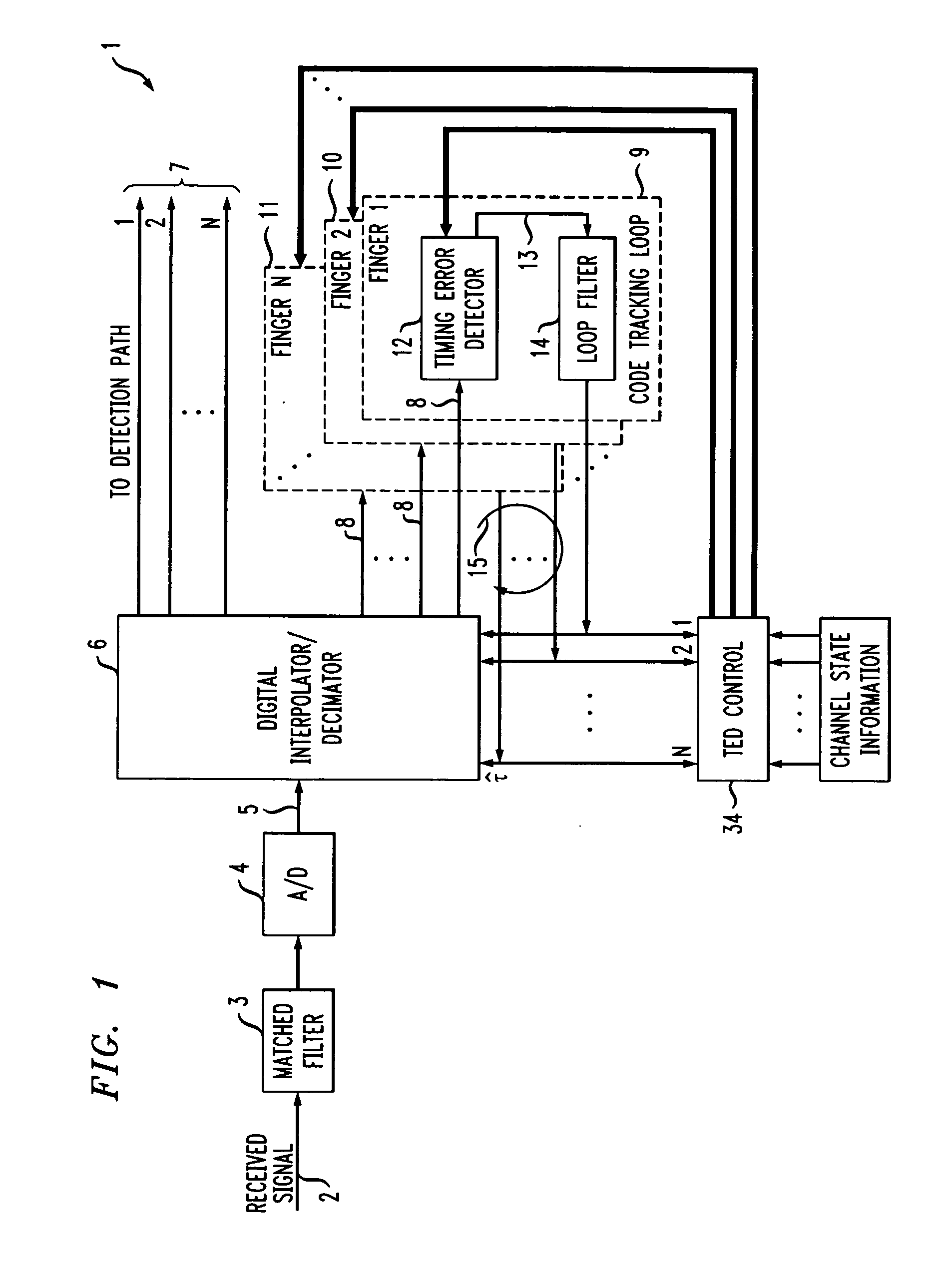
[0036]The invention is part of a tracking device for a digital spread-spectrum rake receiver 1 as shown in FIGS. 1 and 16.

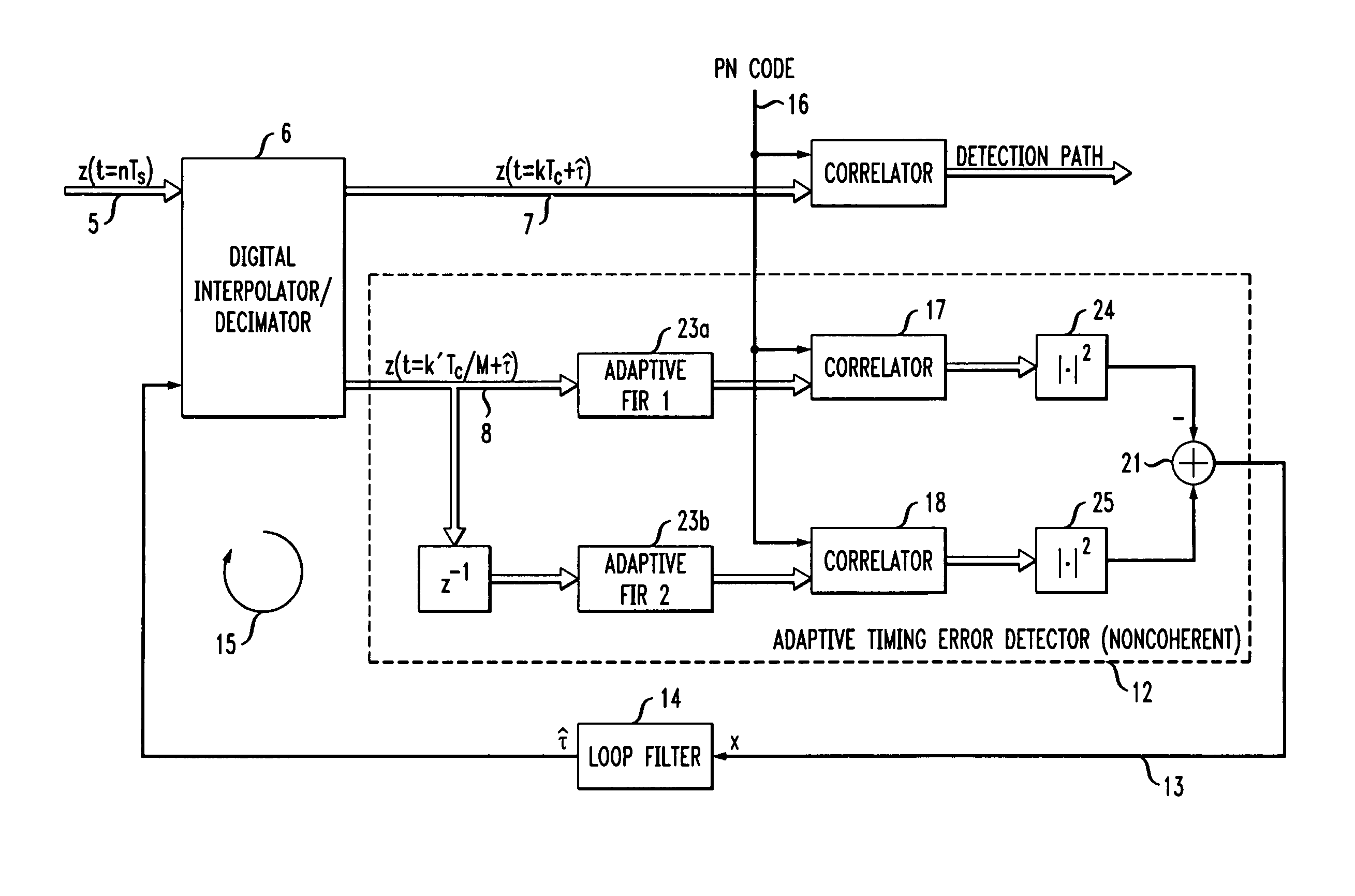
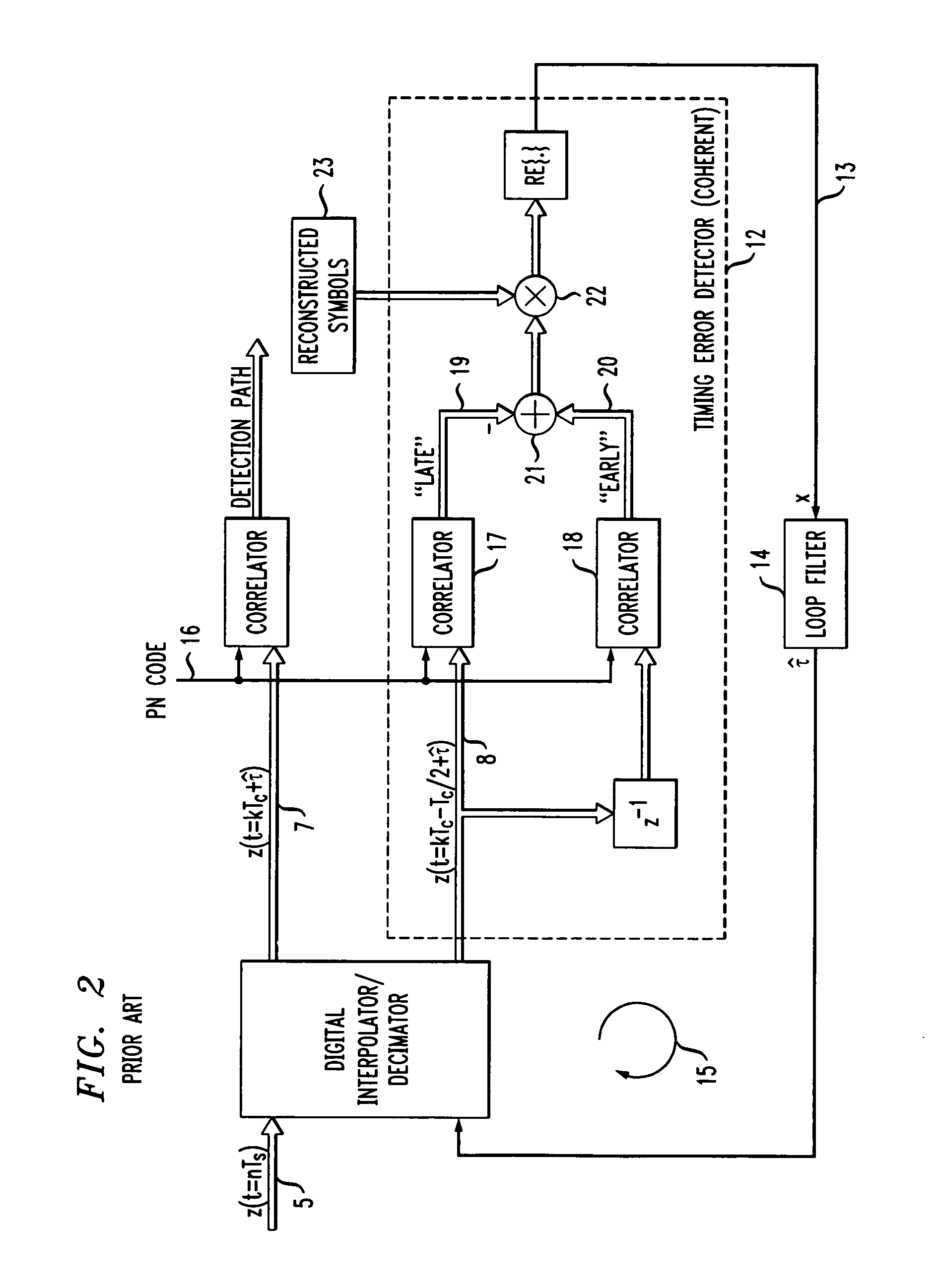
[0037]The incoming signal 2 is fed through a pulse matched filter 3, matched to the transmission pulse. An analog-to-digital (A / D) converter 4 generates equidistant samples 5 of the pulse matched filtered signal and feeds them to a digital interpolator / decimator 6, which generates intermediate samples 7, 8 of the same signal at the estimated timing instants {circumflex over (τ)} for each of the N rake fingers 9, 10, 11.

[0038]The interpolated signal is fed to the detection path 7, where the correlation with the PN-code 16 and symbol detection takes place in each finger 9, 10, 11 as shown in more detail FIG. 16 where essentially only the detection path 7 is shown.

[0039]Furthermore, ...


PUM


Abstract

The invention is directed to a method for signal processing in a rake receiver for spread spectrum signals and is directed to a rake receiver for spread spectrum signals including a plurality of rake fingers (9, 10, 11) each rake finger being adapted to receive a signal (7, 8) being part of a multipath signal (2) and associated with a path of the multipath, the signal (7, 8) having a delay (τ) relative to an other signal associated with an other path of the multipath (7, 8), the receiver comprises a summation unit (37) for generating an output signal from the signals received from of at least some of the rake fingers (9, 10, 11), the output signal being a summation signal having and improved signal to noise ratio (SNR) if compared with the signal to noise ratio (SNR) of at least, one of the rake fingers (9, 10, 11), a timing error detector (12) for detecting a delay (τ) between signals of at least two rake fingers (9, 10, 11) and for generating a timing error signal which is sent to a unit (6) for compensating the error of the respective delay (τ); to provide a code-tracking unit for a direct-sequence code division multiple access (DS-CDMA) receiver having an improved tracking performance, especially in cases where delay times of multipath signals are in the order of the chip duration the timing error detector (12) generates a timing error signal (x, 13) based on the signals (7, 8) associated with paths of the multipath of more than one rake finger (9, 10, 11).

Description

CROSS-REFERENCE TO RELATED APPLICATIONS[0001]This application claims priority of European Patent Application No. 00300268.0, which was filed on Jan. 14, 2000.DESCRIPTION [0002]1. Field of the Invention[0003]The invention is directed to a method of signal processing in a rake receiver and to a direct-sequence code division multiple access (DS-CDMA) receiver in general and especially to a direct-sequence code division multiple access (DS-CDMA) receiver for mobile cellular communications.[0004]2. Prior Art[0005]Spread-spectrum communications systems have been used for many decades, at first because of the excellent anti-jamming properties, but lately because of several advantages in multiple-access scenarios such as cellular communications. In a spread-spectrum system, pseudo-noise code signals (PN code) are used to modulate the data signal, where the bandwidth of the former is substantially larger than that of the latter. The PN code can be used to modulate the carrier frequency, call...

Claims


Application Information

Patent Timeline
Patent Type & Authority Patents(United States)
IPC IPC(8): H04B1/69H04B1/707
CPCH04B1/7085H04B1/7115H04B1/7117
Inventor BALTERSEE, JENSFOCK, GUNNARSCHULZ-RITTICH, PETER
Owner LUCENT TECH INC
Why Eureka
Try Eureka