Exhaust reductant generation in a direct injection engine with cylinder deactivation

a direct injection engine and reductant technology, applied in machines/engines, electrical control, non-mechanical valves, etc., can solve the problems of difficult to determine how much fuel and/or air is actually exhausted, the combustion air-fuel ratio may be too rich or too lean, and the potential disadvantage of such an approach is recognized. , to achieve the effect of reducing the interruption of combustion air-fuel

Active Publication Date: 2006-12-05
FORD GLOBAL TECH LLC
View PDF10 Cites 57 Cited by
  • Summary
  • Abstract
  • Description
  • Claims
  • Application Information

AI Technical Summary

Benefits of technology

[0008]Again, such operation enables the ability to generate unburned hydrocarbons in an engine's exhaust during cylinder deactivation ...

Problems solved by technology

However, the inventors herein have recognized a potential disadvantage with such an approach, at least under some conditions.
For example, it can be difficult to determine how much fuel and/or air is actually exhausted during t...

Method used


Image

  • Exhaust reductant generation in a direct injection engine with cylinder deactivation
  • Exhaust reductant generation in a direct injection engine with cylinder deactivation
  • Exhaust reductant generation in a direct injection engine with cylinder deactivation

Examples


Embodiment Construction

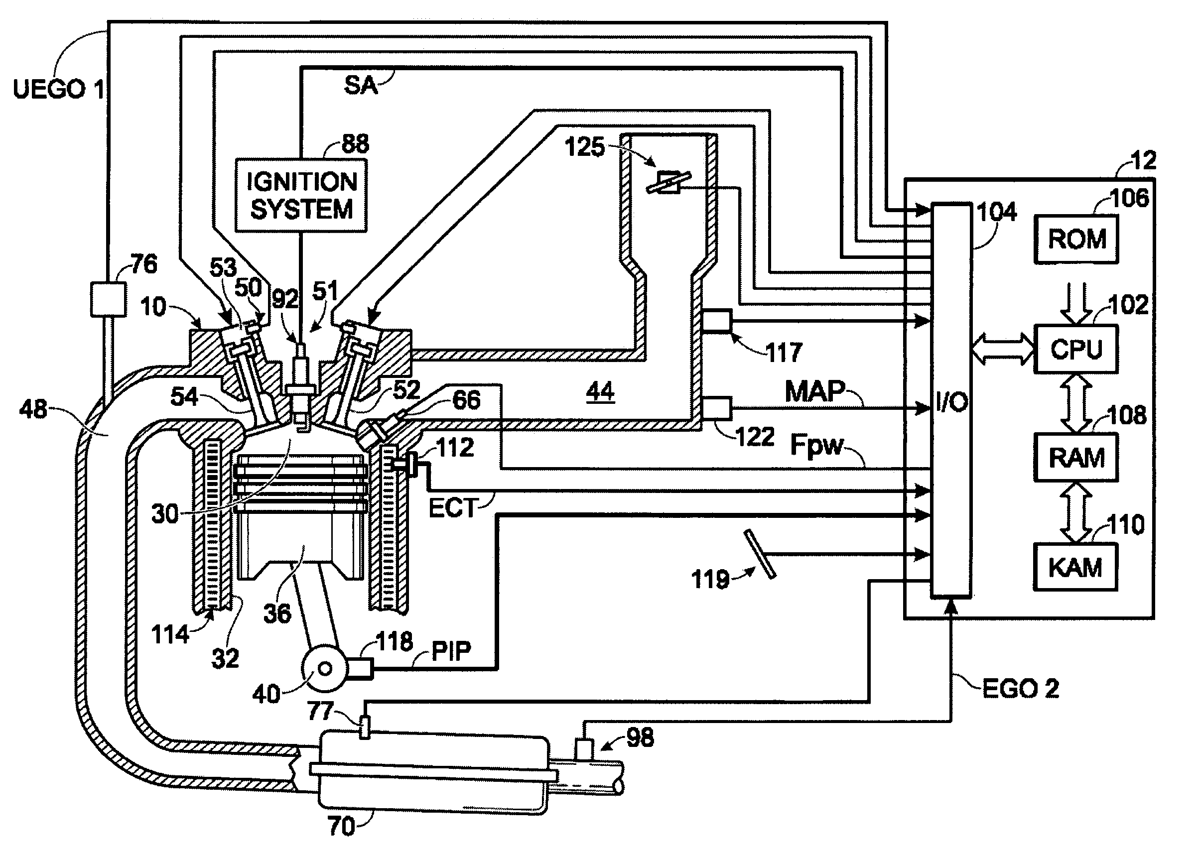
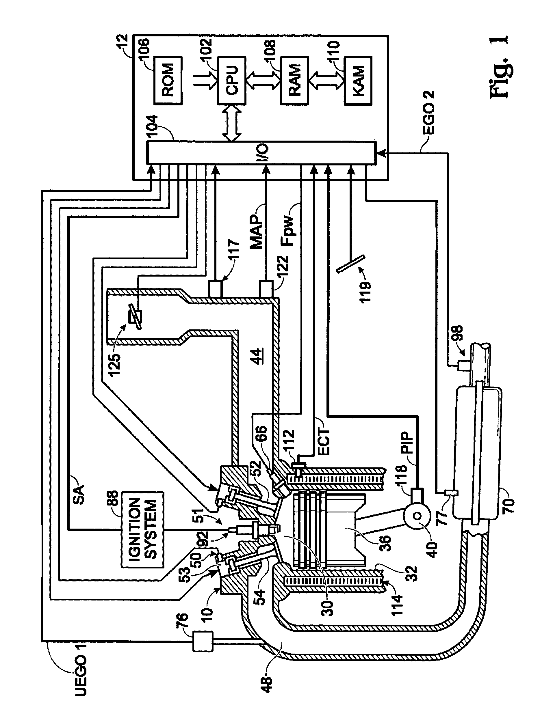
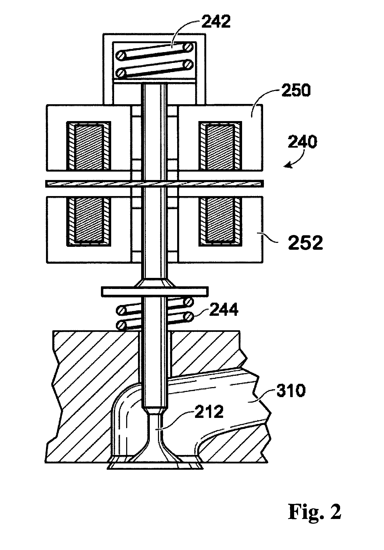
[0015]Referring to FIG. 1, internal combustion engine 10, comprising a plurality of cylinders, one cylinder of which is shown in FIG. 1, is controlled by electronic engine controller 12. Engine 10 includes combustion chamber 30 and cylinder walls 32 with piston 36 positioned therein and connected to crankshaft 40. Combustion chamber 30 is shown communicating with intake manifold 44 and exhaust manifold 48 via respective intake valve 52 an exhaust valve 54. Each intake and exhaust valve is operated by an electromechanically controlled valve coil and armature assembly 53, such as shown in FIG. 2. Armature temperature is determined by temperature sensor 51. Valve position is determined by position sensor 50. In an alternative example, each of valves actuators for valves 52 and 54 has a position sensor and a temperature sensor.

[0016]Intake manifold 44 is also shown having fuel injector 66 coupled thereto for delivering liquid fuel in proportion to the pulse width of signal FPW from cont...


PUM


Abstract

A method for operating an internal combustion engine having at least a first and second cylinder, comprising during at least one operating condition, operating the first cylinder to receive directly injected fuel, mix said fuel with fresh air inducted past an intake valve of the first cylinder, combust said mixture, and exhaust at least a portion of said mixture past an exhaust valve of the first cylinder, and concurrent with said operation of the first cylinder, operating the second cylinder to hold an intake valve of the second cylinder closed for at least a cycle of said second cylinder, receive directly injected fuel, and then exhaust at least a portion of said fuel past an exhaust valve of the second cylinder to generate unburned reductants in an exhaust of the engine.

Description

FIELD[0001]The present application relates to a system and method for controlling engine operation to generate a rich exhaust gas.BACKGROUND AND SUMMARY[0002]Engines use various types of emission control devices to treat emissions in exhaust gas. The devices may use various types of materials to treat emissions, including precious metals and other catalysts. In some types of devices, the materials may have the ability to chemically or physically store oxidants, such as oxygen and / or NOx, during certain operating conditions. For example, some devices store oxidants during excess oxygen conditions. Likewise, some devices may release and / or convert stored oxidants under stoichiometric or oxygen deficient conditions.[0003]Under some conditions, it may be desirable to generate a rich exhaust gas mixture to release and / or convert stored oxidants in an emission control device coupled to an engine's exhaust. One approach that attempts to reduce NOx in a catalyst is described by U.S. Pat. No...

Claims


Application Information

Patent Timeline
IPC IPC(8): F01L1/34F02D13/06F02D17/02F02D7/00
CPCF01L9/04F01L13/0005F01N3/0842F02D13/06F02D17/02F02D41/0087F02D41/0275F01N3/0814F01N13/10F01N2430/02F01N2430/10Y02T10/18F01L9/20Y02T10/12
Inventor WINSTEAD, VINCELEWIS, DONALD J.
Owner FORD GLOBAL TECH LLC
Why Eureka
Try Eureka