Dental tool with shear pin handle

a technology of dental tools and handles, applied in the field of medicine, can solve the problems of inability to reuse, and achieve the effects of preventing the loss of components, preventing the aspiration of any components, and high device accuracy

Inactive Publication Date: 2006-12-05
WALTON JAMES
View PDF16 Cites 13 Cited by
  • Summary
  • Abstract
  • Description
  • Claims
  • Application Information

AI Technical Summary

Benefits of technology

[0013]Disclosed is a torque wrench used to torque direct threading abutments or screw retained abutments which are affixed to dental implants or other prosthesis. The tool is comprised of a cylindrical handle with enlarged working head, through which a cross-bore is countersunk and tapped with left handed threads. The cross-bore is larger at its entrance than its exit. Within this cross-bore, a retaining screw, a shear pin and a drive shaft are engaged one to the other and are retained inside the working head of the handle by the left hand threads of the retaining screw engaging the left hand threads tapped into the cross-bore of the handle. The drive shaft protrudes from the exit of the cross-bore in the handle. The shear point of the shear pin and the entire drive shaft are devoid of contact with any portion of the handle. To use the device, the drive end of the drive shaft is engaged into the socket of a direct threading abutment or the retaining screw of a screw retained abutment. The handle is turned clockwise until the shear pin shears at the shear zone. A novel feature of the device is that the drive shaft and shear zone are isolated from any contact with the wrench handle during use. Because of this, no undesirable and unpredictable frictional forces are added to the torque necessary to shear the shear pin, and which are subsequently transferred to the abutment retaining screw, direct threading abutment or threaded fastener via the drive shaft. Additionally, the design of the shear zone on the shear pin as a circle and not a cylinder, by the machining of a knife edged groove into the shear pin forces shear at an exact diameter and cross sectional area. These features along with the shear pin's material which is best made from Alloy 360 brass all contribu

Problems solved by technology

By design, since it shears u

Method used


Image

  • Dental tool with shear pin handle
  • Dental tool with shear pin handle
  • Dental tool with shear pin handle

Examples


Embodiment Construction

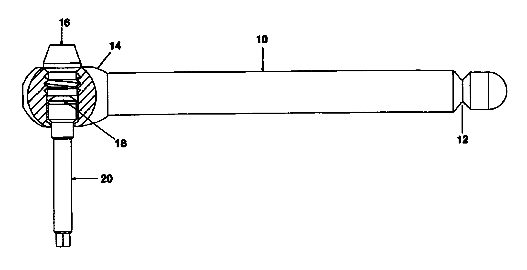
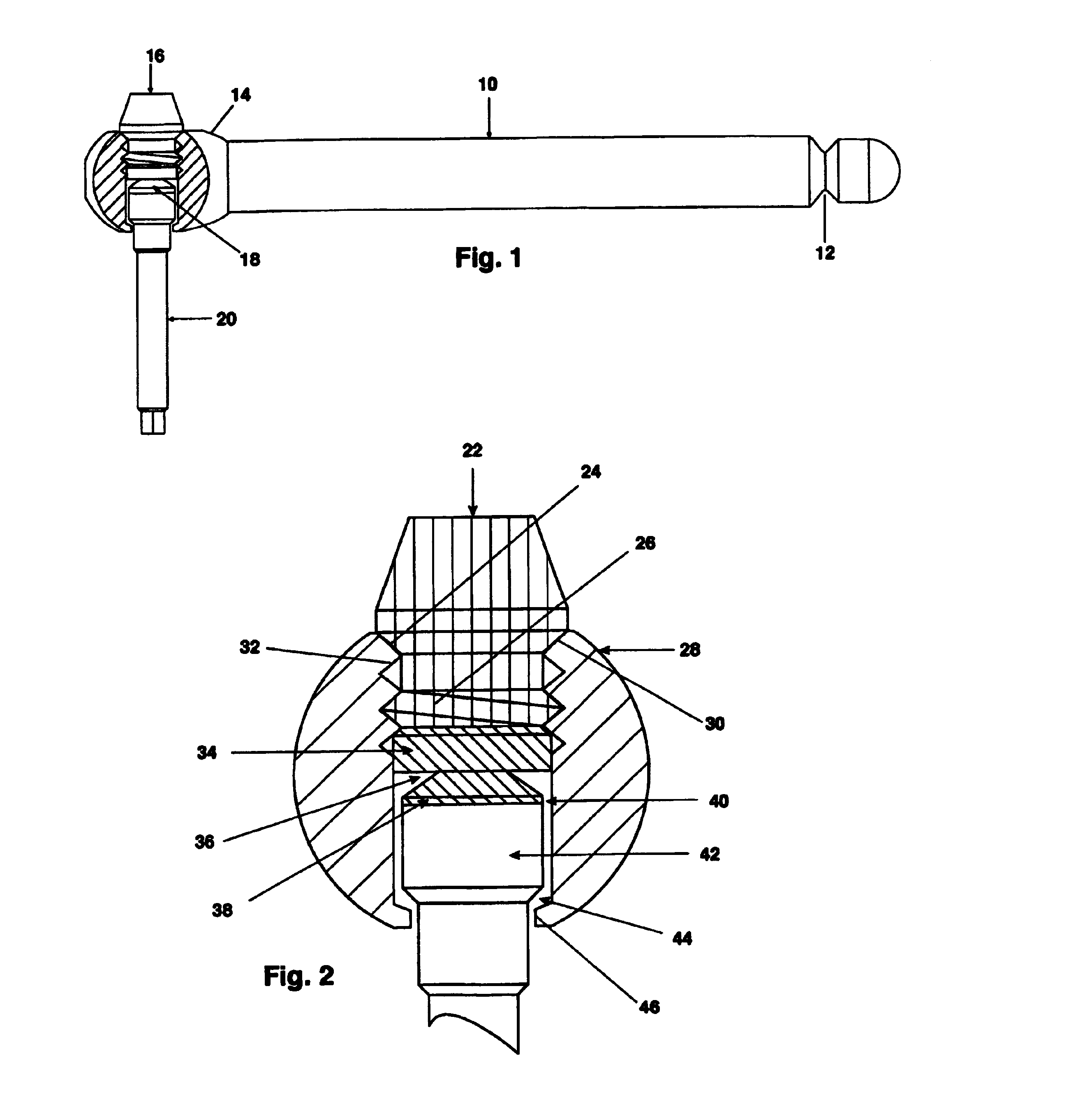
[0030]FIG. 1 shows a side view of the preferred embodiment of the entire invention with a cutaway showing all the components of the invention assembled and ready for use. The wrench handle 10 is generally of cylindrical shape and made of a sufficiently strong material to deliver the proper amount of torque for the application, preferably made from stainless steel or titanium. Safety groove 12 is incorporated into the wrench handle to allow dental floss to be tied around it to prevent aspiration of the entire device as the invention is rather small in overall size. Enlarged head 14 is incorporated into the wrench handle to provide sufficient material to enclose retaining screw 16, shear pin 18 and drive shaft 20.

[0031]FIG. 2 shows an enlargement of the cutaway shown in FIG. 1. The retaining screw 22, is preferably made from stainless steel or titanium although other materials would be suitable, with a tapered head, a countersink portion 24 which seats into a corresponding countersink...


PUM


Abstract

A tool is used to limit the torque applied to tighten the threaded connection of prosthesis components placed in skeletal bones, for example dental implants. The device had a handle, a retaining screw, a single use torque limiting shear pin and a drive shaft. The handle has a tapered counter sunk cross bore with left handed threads to allow installation of a drive shaft which engages a torque limiting shear pin which, in turn, engages a left hand threaded retaining screw. The drive shaft extends from the handle to engage any threaded fastener that has a head that corresponds to the drive shaft end. The drive shaft and the shear zone of the shear pin are completely isolated within the wrench handle so that all rotational force is utilized in the actual shearing of the shear pin to a torque accuracy of ±0.3 Ncm, approximately.

Description

BACKGROUND OF THE INVENTION[0001]This invention relates to the field of medicine, for example, dentistry, and the mounting of all types of prostheses to osseointegrated implants.[0002]Tooth loss in humans is an unfortunate fact of life for a large portion of the population. The concomitant loss of masticatory function and esthetics is a very real problem that has only been able to be effectively addressed by various treatment modalities in modern times. Traditional restorative treatment for tooth loss has been placement of fixed partial prostheses (bridgework), removable partial prostheses (partial dentures), and complete removable prostheses (complete dentures). The main shortcoming of all of these treatment modalities is the lack of underlying bone support for the prosthetic replacement, making the stability of some prostheses tenuous at best.[0003]Osseointegrated dental implants have vastly improved this situation by providing solid bone support for all of the types of prostheses...

Claims


Application Information

Patent Timeline
IPC IPC(8): A61C3/00B25B23/143A61C8/00A61B17/88A61B19/00A61C1/18B25B23/14B25B23/153
CPCB25B23/1415A61C8/0089A61B17/8875A61C1/186A61B2090/031
Inventor WALTON, JAMES
Owner WALTON JAMES
Why Eureka
Try Eureka