Electrical power system for vehicles requiring electrical power while the vehicle engine is not in operation

a technology of electric power system and vehicle engine, which is applied in the direction of engine starter, battery/fuel cell control arrangement, machines/engines, etc., can solve the problems of electric power requirements and achieve the effect of reducing battery power capacity

Active Publication Date: 2006-12-05
PACCAR INC
View PDF8 Cites 54 Cited by
  • Summary
  • Abstract
  • Description
  • Claims
  • Application Information

AI Technical Summary

Benefits of technology

[0012]One important aspect of the invention is maintaining the batteries that power the vehicle hotel loads in a controlled thermal environment to ensure battery operation at or near maximum power capacity regardless of ambient temperature. In accordance with this aspect of the invention, the batteries are contained in a thermally insulated enclosure and are heated to a predetermined temperature by electrical heating elements when the vehicle engine is in operation. During periods in which the vehicle engine is not running and battery power is being made available for hotel loads, the insulated enclosure maintains the temperature of the batteries high enough to prevent a significant decrease in battery power capacity even when the ambient temperature is well below freezing. In the disclosed exemplary embodiments of the invention, the battery heaters are connected to the vehicle power system by means of a relay that is energized and de-energized to control battery temperature. A voltage regulator includes an arrangement for determining battery temperature based upon a signal supplied by a temperature sensor that is mounted to one of the battery posts and energizes and de-energizes the relay so that the batteries are maintained at or near the desired predetermined temperature (e.g., 85° F.; approximately 29° C. in the currently preferred embodiments of the invention).
[0013]The preferred embodiments of the invention do not use the vehicle batteries to start the vehicle engine, using instead a large capacitor that is often referred to as an “ultra-capacitor.” In the currently preferred embodiments of the invention, the fully charged terminal voltage of the ultra-capacitor is established by an up / down dc-to-dc converter that is electrically connected between the vehicle batteries and the ultra-capacitor. In these embodiments, the fully charged terminal voltage of ultra-capacitor is a predetermined voltage (a design value) that is less than the maximum output voltage of the vehicle alternator and is greater than a voltage that indicates the batteries are in a discharged state. When the alternator voltage is above the predetermined fully charged ultra-capacitor voltage, the dc-to-dc converter down converts the alternator voltage to the predetermined fully charged ultra-capacitor voltage. On the other hand, when the system is supplying current to hotel loads and the battery voltage falls below the voltage that indicates a discharged state, the dc-to-dc converter up converts the battery voltage to maintain the capacitor charging voltage equal to the predetermined value. Further, in the most preferred embodiments, the dc-to-dc converter includes circuitry for monitoring the dc current being supplied to the ultra-capacitor. When the charging current falls to a level that indicates that the ultra-capacitor is fully charged, the dc-to-dc converter is de-energized and remains off until the capacitor voltage falls below the predetermined ultra-capacitor charging voltage (which may be caused by capacitor self discharge or engine start). Also included in the dc-to-dc converter is circuitry for energizing a light-emitting diode (LED) to indicate the capacitor is fully charged and available for starting the truck. De-energizing the dc-to-dc converter eliminates dc-to-dc converter quiescent current during periods of time in which the ultra-capacitor is fully charged, thereby conserving energy for use in powering the hotel loads.
[0014]Another aspect of the invention relates to packaging of the electrical power system for ease of deployment in a long-haul truck or other vehicle. In particular, the electrical power system can be arranged in a variety of modular configurations that are suitable for installation at the time of vehicle manufacture or as an after market addition to an existing vehicle. In one disclosed arrangement, the batteries and all other components of the electrical power system are mounted within an insulated enclosure even though the operation of the ultra-capacitor and other system components are not adversely affected by ambient temperature. One advantage of such an arrangement is that the thermal mass of the ultra-capacitor and other components provides an additional source of thermal energy to maintain the interior of the insulated enclosure and, hence, the batteries, within a desired temperature range when the vehicle engine is not running and power is being made available for the hotel loads. In another disclosed embodiment, the ultra-capacitor is mounted in an enclosure that is somewhat similar to a conventional battery box that is located near the engine starter motor. In that particular embodiment, only the system batteries and battery heater are contained in an insulated enclosure with the insulated enclosure and the remaining electrical power system components being configured as a module that can easily be installed in a long-haul truck or other vehicle.

Problems solved by technology

As is known in the art, such devices are fuel efficient, with electrical power requirements being limited to current sufficient to operate a small blower motor and fuel pump.

Method used


Image

  • Electrical power system for vehicles requiring electrical power while the vehicle engine is not in operation
  • Electrical power system for vehicles requiring electrical power while the vehicle engine is not in operation
  • Electrical power system for vehicles requiring electrical power while the vehicle engine is not in operation

Examples


Embodiment Construction

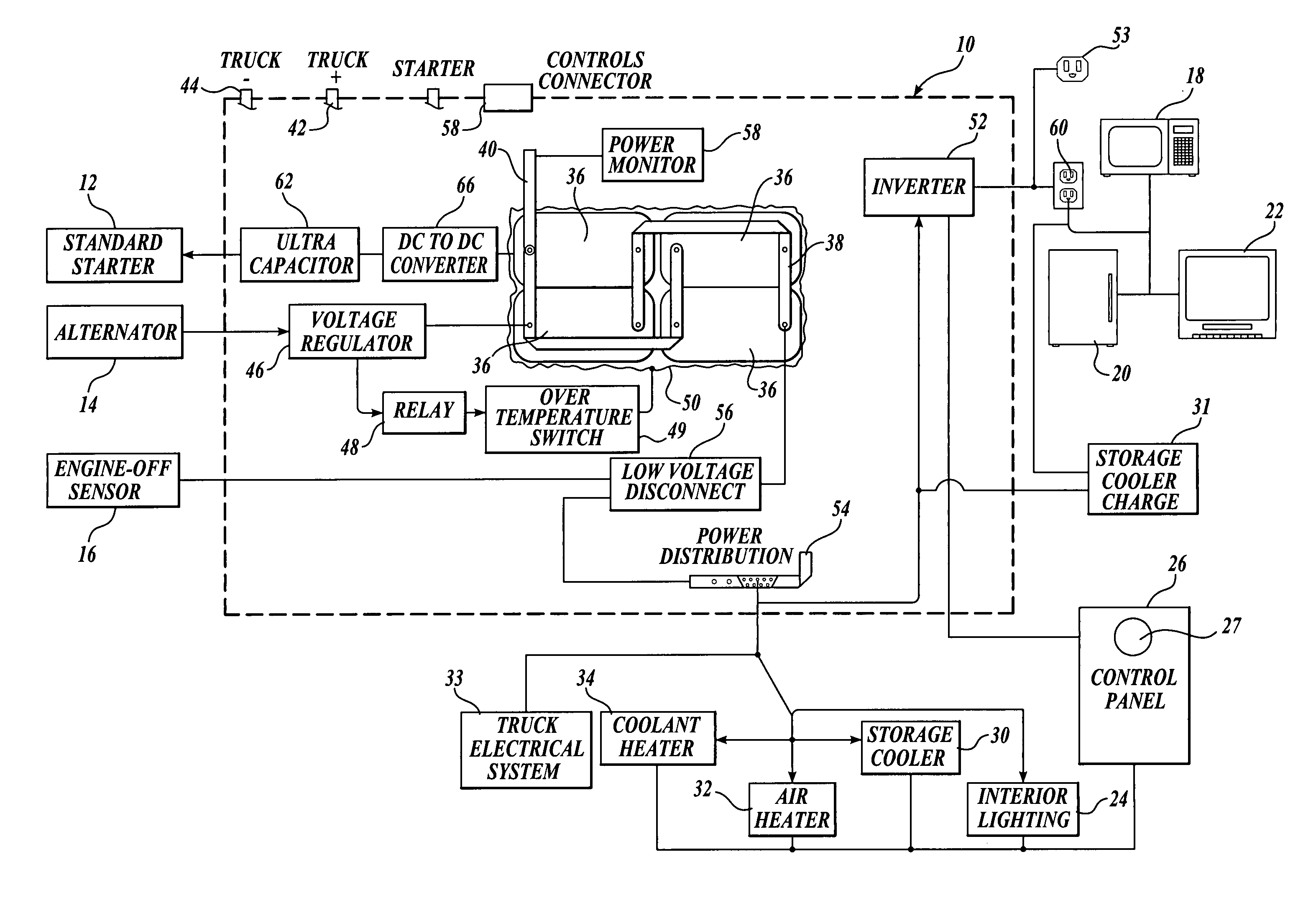
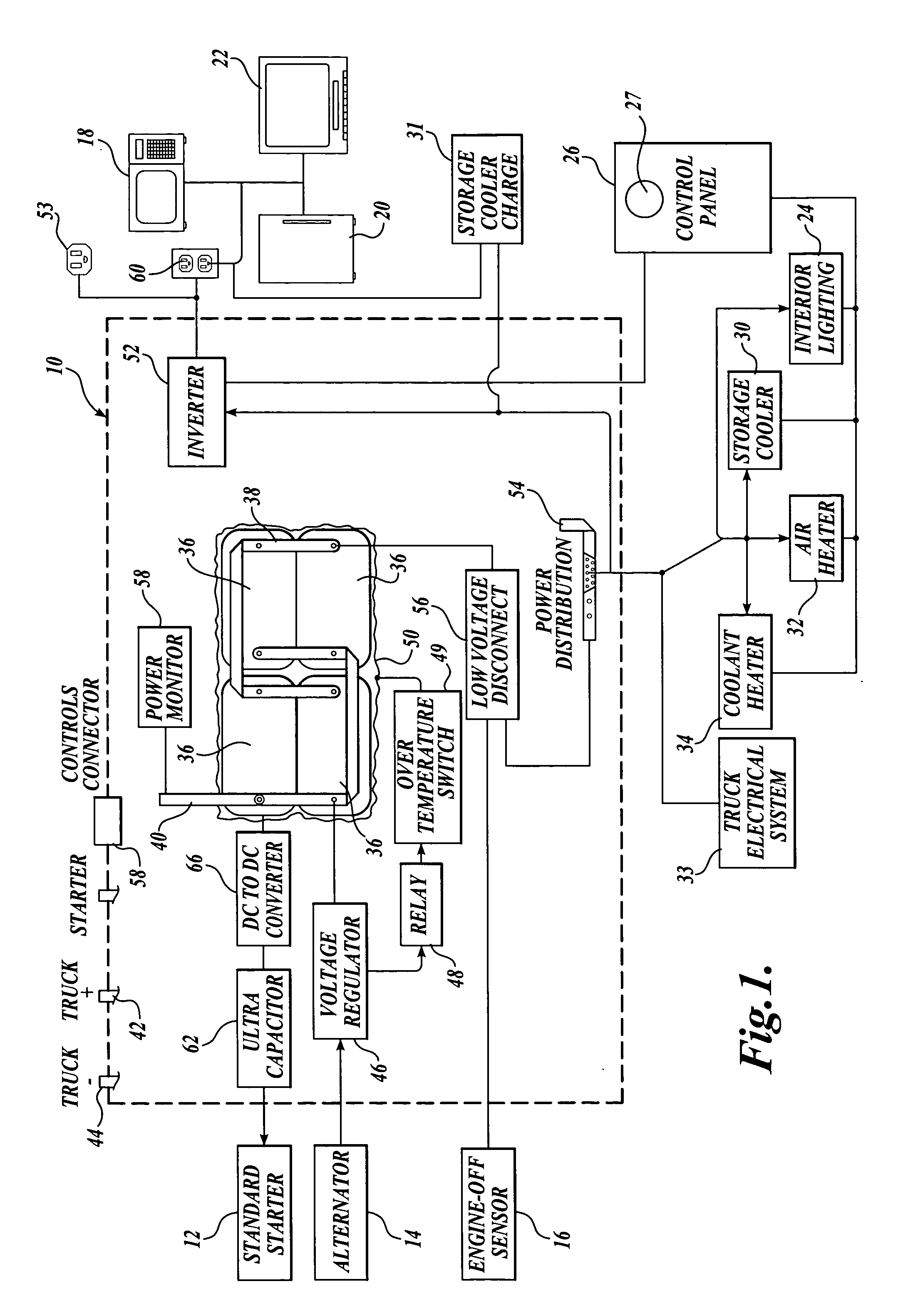
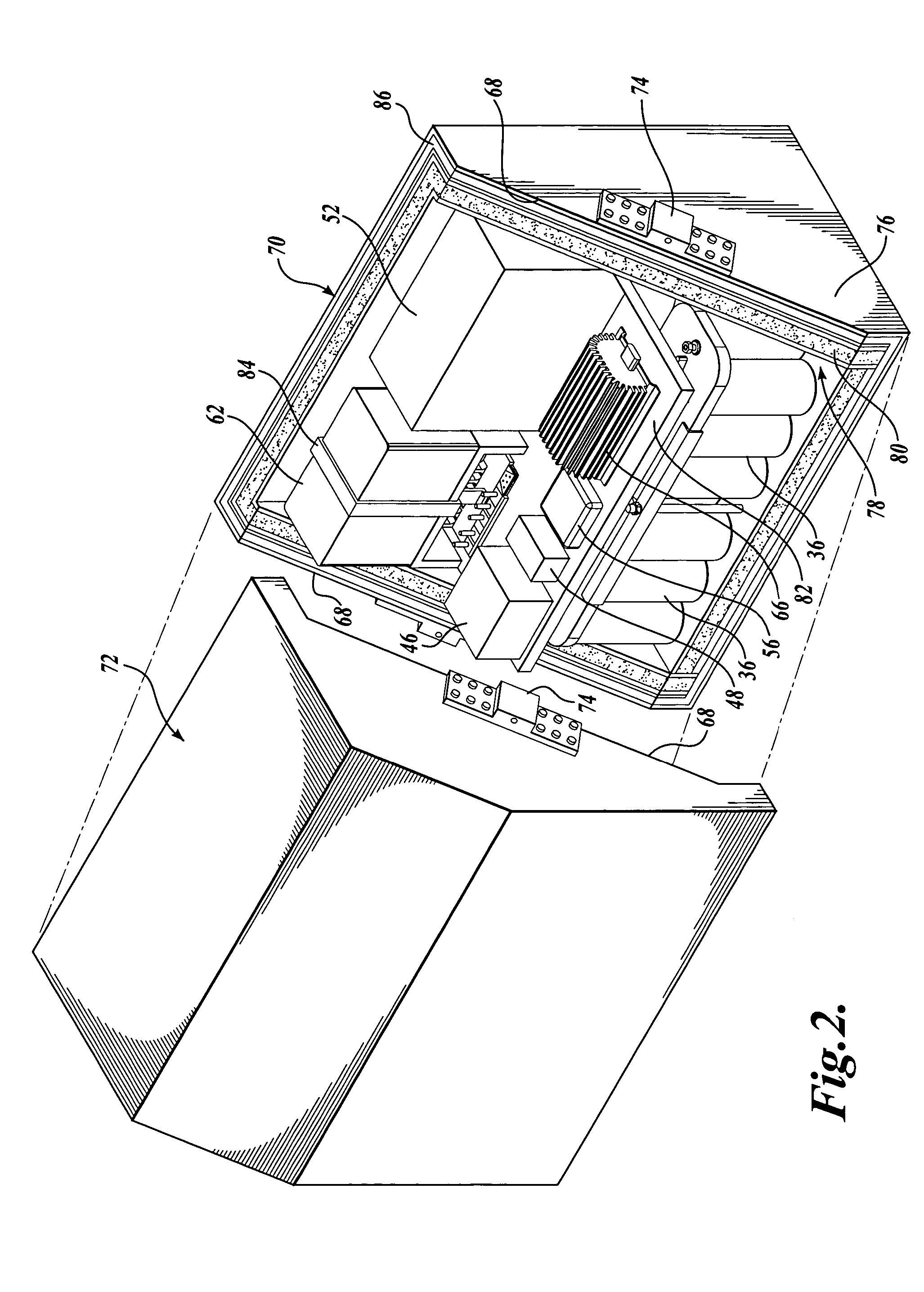
[0024]FIG. 1 is a diagram that illustrates an embodiment of the invention configured for installation in a vehicle such as a diesel powered long-haul truck that is equipped with a sleeper cab. Components of the electrical power system of the invention are shown within dashed outline 10. As shall be described relative to FIG. 2, in one physical realization of the invention, all components of the power system shown within dashed outline 10 are contained within an insulated enclosure that thermally isolates the batteries of the power system from the thermal environment in which the enclosure is mounted. In another physical realization of the invention (shown in FIG. 3), only the system batteries are contained in an insulated enclosure.

[0025]Located outside dashed outline 10 of FIG. 1 are the truck starter motor 12, the truck alternator 14, and an engine-off sensor 16. Also shown outside dashed outline 10 are electrically powered hotel loads of the type involved with practicing the inve...


PUM


Abstract

A system for supplying electrical power for use when the vehicle engine is shut down and configurations of long-haul trucks employing the system are disclosed. The power system is a battery bank contained within an insulated enclosure. The batteries are heated when the truck is in operation with the insulated enclosure maintaining battery temperature sufficient to provide high battery power capacity for an extended period after the vehicle is shut down. A large capacitor, rather than the batteries, provides current for starting the vehicle engine. A dc-to-dc converter controls the fully charged capacitor voltage and provides capacitor charging current even when the batteries have been discharged to a low-voltage condition. The disclosed long-haul truck configurations include a storage cooler that employs a phase-change medium that is thermally charged to a low temperature while the truck is in operation and is used to provide sleeper unit cooling air. Additional provision is made for heating the sleeper unit and for powering a coolant heater that can warm the truck engine block and truck fuel when the engine is shut down during cold weather.

Description

FIELD OF THE INVENTION[0001]The present invention relates to vehicles in which electrical power is supplied to various loads when the vehicle is not underway and to electrical power systems for supplying power to such loads.BACKGROUND OF THE INVENTION[0002]Various vehicles such as long-haul trucks, boats and recreational vehicles are equipped with electrical and electronic equipment that require power when the vehicle is underway and when it is parked. Such devices are often referred to as “hotel loads,” and include heating and air conditioning, lighting, and appliances such as refrigerators, coffee makers and microwave ovens as well as television and entertainment systems. Although the vehicle engine can be left running at idle to provide power for hotel loads, the result is undesired fuel consumption, engine wear and the emission of pollutants. Thus, over the years, various arrangements have been proposed to supply power to vehicle hotel loads while the vehicle engine is not runni...

Claims


Application Information

Patent Timeline
Patent Type & Authority Patents(United States)
IPC IPC(8): H02M1/00B60R16/04F02N11/06
CPCB60H1/00278B60H1/00378B60L1/02B60L11/1872B60H1/00271B60L2210/20Y02T10/7005Y02T10/705Y02T10/725B60L58/25Y02T10/70Y02T10/72
Inventor PLUMMER, LEW E.
Owner PACCAR INC
Why Eureka
Try Eureka