Method and system for implementing a circuit design in a tree representation

a tree representation and circuit design technology, applied in the field of circuit design, can solve the problems of increasing the complexity and size of fpga design, complex xilinx fpga devices, and the complexity of circuit designs, and achieve the effect of simplifying the interface of circuit designs to the underlying net-list information

Active Publication Date: 2006-12-05
XILINX INC
View PDF14 Cites 44 Cited by
  • Summary
  • Abstract
  • Description
  • Claims
  • Application Information

AI Technical Summary

Benefits of technology

[0014]The notion of Implementation Set (I-Set) is being introduced to provide a common and singular paradigm for which all interactive flows can operate upon. I-Set exploits the notion of implementation granularity and provides a flow independent concept to how a partial net-list is specified. In other words, embodiments in accordance with the invention removes dependencies between high-level flow requirements and low-level tasks as it relates to the electronic design process for integrated circuits. By providing a unifying data model such as I-Set, client applications (such as design tools) can significantly simplify their interface to the underlying net-list information. Effectively, client applications no longer need to distinguish between different net-list entities such as user floor planned partitioning (e.g., area groups), modules, and flat designs in its implementation. Client applications such as design implementation tools can focus solely on I-Sets instead of being concerned with flow information and the different net-list entities associated with partial net-lists. A software tool can be used to determine a list of (flow independent) tasks needed to manipulate the containers. Furthermore, embodiments in accordance with the present invention involves the I-Sets and the introduction of a tree representation to represent the implementation dependencies among portions of the design and its use for various design implementation methodologies. To implement portions of the design sequentially and to complete the implementation of the entire design, two systematic ways to traverse the implementation tree can be used where each traversal generates an implementation sequence. To implement portions of a design in parallel, a proposed implementation tree can be used to identify the sets of partial designs that can be implemented independently. The methods introduced herein can apply to software programs that implement IC designs including, but not limited to PLD, ASIC, and gate array designs implementations.
[0015]An exemplary embodiment of the present invention involves a method of implementing a user integrated circuit (IC) design in a tree representation including the steps of introducing the tree representation for the user IC design in a partitioned manner including at least one sub-design to form a design abstraction of the user design. At least one sub-design can include a sub-design providing for multiple levels of implementation hierarchy. The method can further include the step of traversing the design abstraction in a top-down fashion to provide functions selected among floor planning, port assignment, and timing budgeting for at least one sub-design, and the step of traversing the design abstraction in a bottom-up fashion to facilitate at least one among resolution of resource conflicts and parallel processing of multiple sub-designs. The step of traversing the design abstraction in the bottom-up fashion can also facilitate a re-budgeting of timing for the integrated circuit design. Note, the user IC design can be for FPGAs, ASICs, PLDS, or other IC devices.
[0016]In another embodiment of the present invention a method of implementing an IC design includes the step of expressing a desired hierarchical relationship in a form of parent-child pairs where a parent sub-design is dependent upon a child sub-design and the desired hierarchical relationship is a design abstraction of the IC design forming an implementation tree. The method further includes the step of traversing the design abstraction in a top-down fashion to provide functions selected among floor planning, port assignment, and timing budgeting for the at least one sub-design and the step of traversing the design abstraction in a bottom-up fashion to facilitate at least one among resolution of resource conflicts and parallel processing of multiple sub-designs.
[0017]In yet another embodiment of the present invention, a integrated circuit design implementation tool for designing integrated circuits can include a memory and a processor. The processor can be programmed to implement an integrated circuit design using an implementation tree having a rooted tree with a plurality of nodes that represents an implementation hierarchy among sub-designs in a design abstraction of the integrated circuit design. The processor can be further programmed to traverse the design abstraction in a top-down fashion to provide functions selected among floor planning, port assignment, and timing budgeting for the at least one sub-design and traverse the design abstraction in a bottom-up fashion to facilitate at least one among resolution of resource conflicts and parallel processing of multiple sub-designs.

Problems solved by technology

Circuit designs, and particularly designs for Field Programmable Gate Arrays (FPGA's), have become increasingly complex and heterogeneous.
The rapid increase of FPGA design complexity and size has driven several complex Xilinx FPGA devices to accommodate a few million gates.
This increasing complexity makes design tools, maintenance of design tools as well as placement and signal routing of circuit designs more cumbersome.
Existing design tools can have multiple flows that fail to be uniform, further adding to the complexity in the tools and their maintenance.
Furthermore, existing design tools fail to provide sufficient flexibility in terms of representing design granularity in a particular design.
With such an enormous increase in device capacity and complexity, the traditional flattened design implementation methodology is faced with challenges in obtaining a good design implementation in an acceptable time frame.
Since the design is flattened and implemented all at once in the traditional flattened design implementation methodology, a design of large size can easily cause a sophisticated algorithm employed in a tool flow to fail in the run-time without guaranteeing a good solution.
Consequently, a divide-and-conquer methodology is usually considered for difficult and perhaps sometimes impossible large design implementations.
Due to historical reasons, each of the user interactive flows has been designed separately and for the most part defect driven.
Without a common theme among these user interactive flows, it was inevitable that the relevant concepts, methodology, and implementation became fractured.
As a result, inefficiencies arose and customer flow complexity increased.
In addition, the internal implementation increased in the development overhead as each user interactive flow was supported separately.
As the result, the client application implementations became dependent of each flow and required the software overhead of understanding and processing the various data representations.
In addition, due to the complexity of each interactive flow, the software maintenance and enhancements became an increasing overhead and burden on engineering staff resources.
As the software system evolves with an increasing number of these design entities, the resulting software complexity and impact will be significant.
Any changes to the high-level flow information will result in changes to the code in many different places that can result in costly coding errors.
Relatively minor changes to the flow can result in major modifications to the underlying algorithms.
Consequently, it is difficult to support new flows or modify existing flows.

Method used


Image

  • Method and system for implementing a circuit design in a tree representation
  • Method and system for implementing a circuit design in a tree representation
  • Method and system for implementing a circuit design in a tree representation

Examples


Embodiment Construction

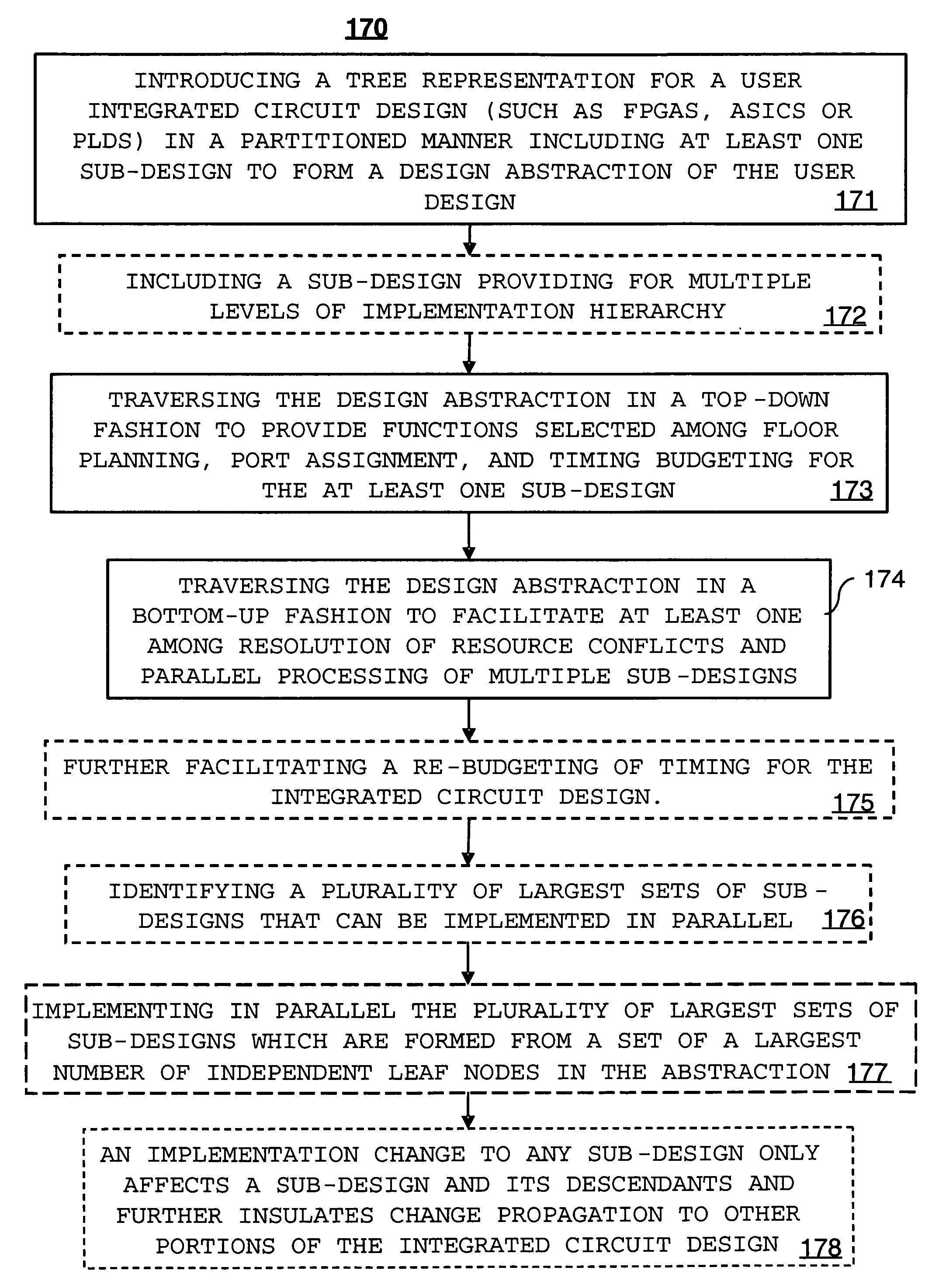
[0038]The present invention provides a solution for simplifying the implementation of circuit designs and associated maintenance without limiting or restricting granularity by using an abstraction called implementation sets or I-Sets.

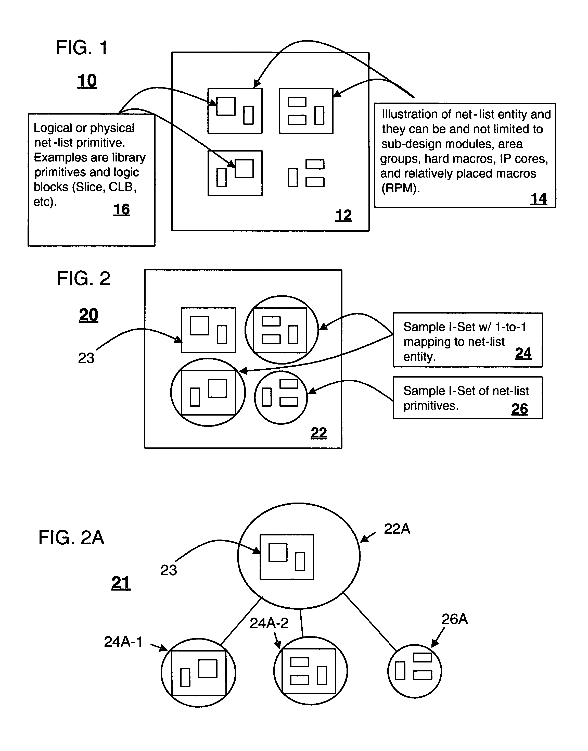
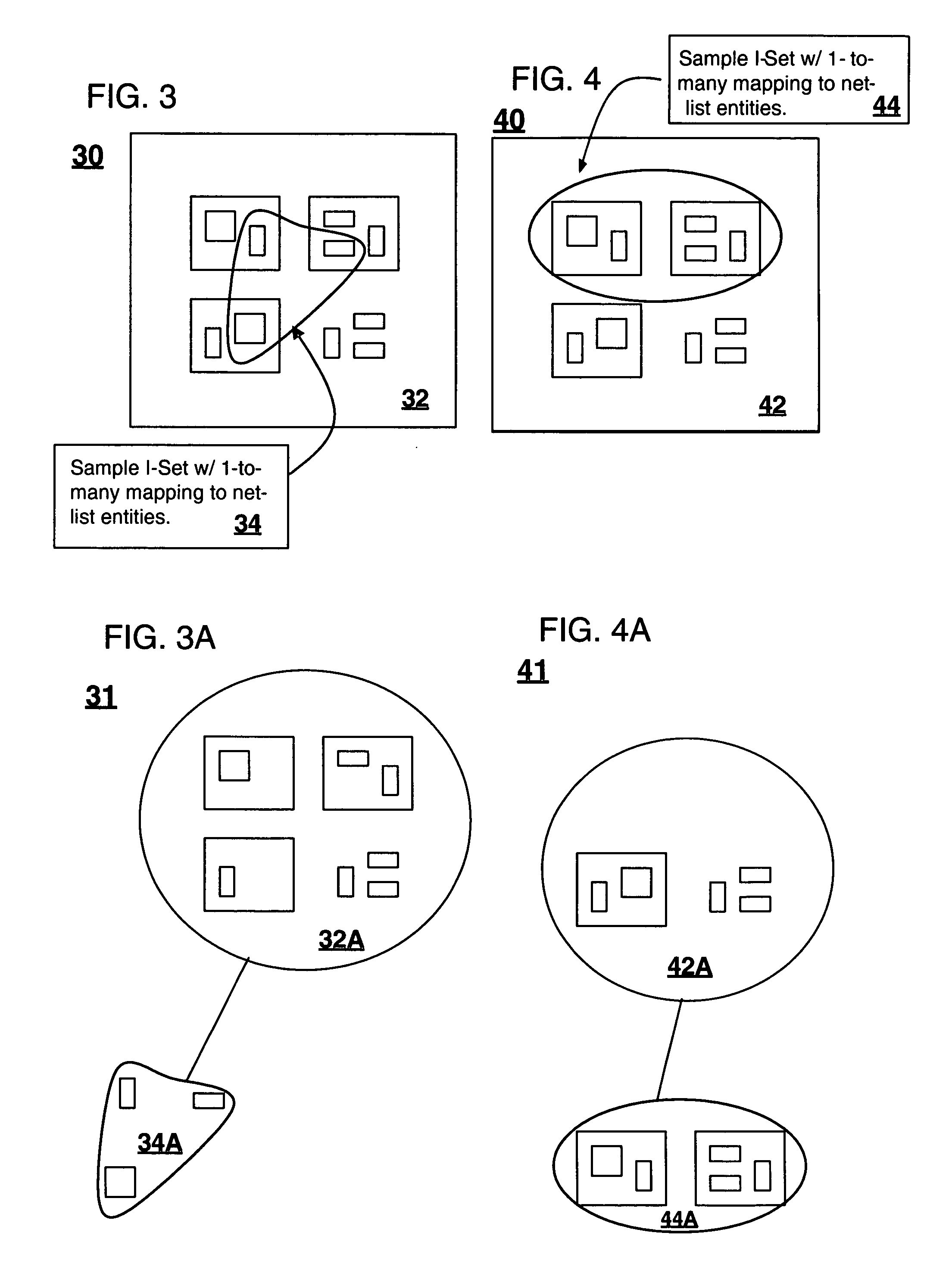
[0039]Circuit designs or circuit design representations can include any physical description of a circuit design in terms of the components to be used, including but not limited to, net-lists, circuit descriptions conforming to open standards such as the Berkeley Logic Interchange Format (BLIF), as well as circuit descriptions conforming to proprietary standards such as Native Circuit Description as used by Xilinx, Inc. of San Jose, Calif. For example, as shown in FIG. 1, a sample circuit design representation 10 can include a circuit design 12 having a plurality of net-list entities 14 such as sub-design modules, user floor planned partitions (e.g., area groups), hard macros, IP cores, and relatively placed macros each having logical or physical net-li...


PUM


Abstract

A method of implementing a user integrated circuit (IC) design in a tree representation includes the step of introducing the tree representation for the user IC design in a partitioned manner including at least one sub-design to form a design abstraction of the user design. At least one sub-design can include a sub-design providing for multiple levels of implementation hierarchy. The method can further include the step of traversing the design abstraction in a top-down fashion to provide functions selected among floor planning, port assignment, and timing budgeting for at least one sub-design, and the step of traversing the design abstraction in a bottom-up fashion to facilitate at least one among resolution of resource conflicts and parallel processing of multiple sub-designs. Traversing the design abstraction in the bottom-up fashion can facilitate a re-budgeting of timing for the integrated circuit design.

Description

BACKGROUND[0001]1. Field of the Invention[0002]The invention relates to the field of circuit design and, more particularly, to the use of implementation sets in a tree representation for implementing a circuit design.[0003]2. Description of the Related Art[0004]Circuit designs, and particularly designs for Field Programmable Gate Arrays (FPGA's), have become increasingly complex and heterogeneous. The rapid increase of FPGA design complexity and size has driven several complex Xilinx FPGA devices to accommodate a few million gates. Modern circuit designs can include a variety of different components or resources including, but not limited to, registers, block Random Access Memory (RAM), multipliers, processors, and the like. This increasing complexity makes design tools, maintenance of design tools as well as placement and signal routing of circuit designs more cumbersome. Existing design tools can have multiple flows that fail to be uniform, further adding to the complexity in the ...

Claims


Application Information

Patent Timeline
Patent Type & Authority Patents(United States)
IPC IPC(8): G06F17/50
CPCG06F17/5045G06F17/5072G06F30/392G06F30/30
Inventor SUN, RICHARD YACHYANGDOWNS, DANIEL J.KONG, RAYMONDLAURENCE, JOHN J.
Owner XILINX INC
Why Eureka
Try Eureka