Supercharge Your Innovation With Domain-Expert AI Agents!

Method to make planarized GMR head for high track density

a technology of magnetic read head and planarized gmr, which is applied in the field of fabrication of giant magnetoresistive (gmr) magnetic read head, can solve the problems of disadvantageous further processing and stringent insulation constraints, and achieve the effect of better control of ion-beam deposition (ibd) and better definition of the track width of the sensor layer

Active Publication Date: 2006-12-12
HEADWAY TECH INC
View PDF9 Cites 7 Cited by
  • Summary
  • Abstract
  • Description
  • Claims
  • Application Information

AI Technical Summary

Benefits of technology

[0011]A third object of this invention is to provide a method for forming such a sensor element that results in planar topologies and corresponding precision, efficiency and ease of fabrication steps.
[0013]In accord with the objects of this invention there is provided a method of forming a GMR read-head wherein a first bi-layer lift-off stencil is used as an etching mask to form concave regions in a lower shield surrounding a central planar portion of said shield. The lift-off stencil is then used as a deposition stencil to allow the concave regions to be filled with an insulation dielectric. After removal of the stencil, the filled-in shield is planarized and a uniform blanket dielectric insulating layer is deposited. The planar dielectric layer provides an advantageous surface for the formation of a GMR layer, which is thin and planar. Finally, a PMGI layer of uniform thickness is formed on the GMR layer and the PMGI layer is patterned to form the pedestal of a second bi-layer lift-off stencil, which will be used to form conducting lead layers and magnetic biasing layers. Because of the thickness uniformity of the PMGI layer, problems with forming a non-uniform upper photoresist layer on the bi-layer stencil will be eliminated, leading to better control of the ion-beam deposition (IBD) of the lead layers and better definition of the track-width of the sensor layer.

Problems solved by technology

The formation of such a sensor layer places stringent constraints on the insulation between the layer and the magnetic shield on which it is typically formed.
In this case, the PMGI attains a non-planar profile with thickness variations shown by arrows (220, 240), which is disadvantageous for further processing.
Such stencils cannot accurately define the edges of the deposited layers and the “overspray” of the deposition beneath the stencil overhang can cause difficulties.

Method used


Image

  • Method to make planarized GMR head for high track density
  • Method to make planarized GMR head for high track density
  • Method to make planarized GMR head for high track density

Examples


Embodiment Construction

[0024]The preferred embodiment of the present invention is a method for forming a GMR read head having a planar sensor element with a thin read-gap and narrow, precisely defined read-width which is well insulated from the bottom magnetic shield on which it is formed.

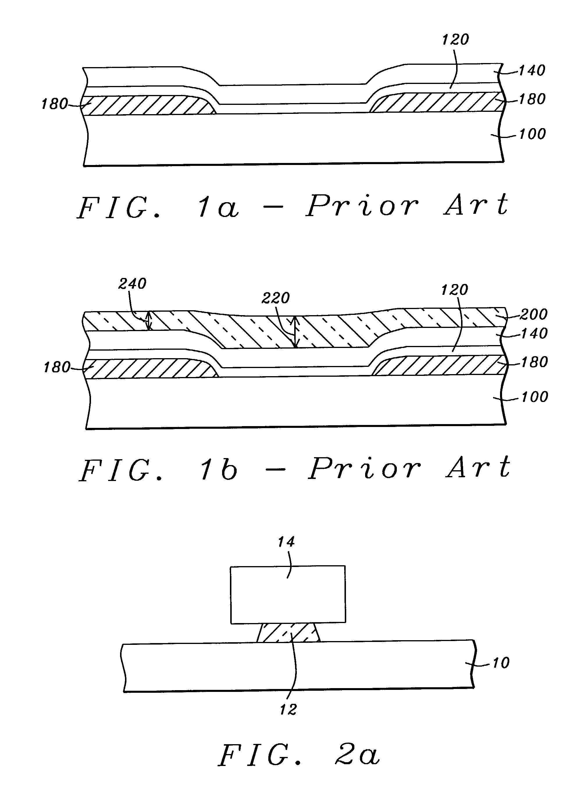
[0025]Referring first to FIG. 2a, there is shown an initial step in the method. The schematic drawing shows a cross-sectional view, in the air-bearing surface plane of the element, of a bottom magnetic shield (10) on which has been formed a bi-layer lift-off stencil of a type well known in the prior art. The stencil will serve, initially, as an ion-beam etching (IBE) mask and then serve, finally, as an ion-beam deposition (IBD) mask. The stencil is formed of a lower pedestal (12) of polydimethylglutamide (PMGI) formed to a thickness of between approximately 1000 and 4000 angstroms, on which is formed an upper portion (14) of photoresistive material. The upper portion overhangs the pedestal on each side and the overhang s...


PUM

PropertyMeasurementUnit
Thicknessaaaaaaaaaa
Dielectric polarization enthalpyaaaaaaaaaa
Densityaaaaaaaaaa

Abstract

A method for forming a planar GMR read-head having a narrow read gap, a narrow track-width and being well insulated from its lower shield. The method requires the formation of a planarized bottom magnetic shield in which concave regions, symmetrically disposed about a track-width region, are filled with a layer of dielectric to provide added insulation. The dielectric filled shield is planarized and an additional planar dielectric layer, a thin planar GMR sensor layer and a planar PMGI layer of uniform thickness is formed on it. A layer of photoresist is deposited on the PMGI layer and a bi-layer lift-off stencil of uniform height above the GMR layer and symmetric overhang regions is formed. The uniformity of the lift-off stencil, which is a result of the planarity of the layers on which it is formed, allows the deposition of conductive lead and biasing layers with controlled overspread.

Description

BACKGROUND OF THE INVENTION[0001]1. Field of the Invention[0002]This invention relates generally to the fabrication of a giant magnetoresistive (GMR) magnetic read head, more specifically to a method of fabrication that allows better control of the sensor read-width while still maintaining a high level of insulation between the sensor and the lower shield.[0003]2. Description of the Related Art[0004]As GMR (giant magneto-resistive) magnetic read heads are required to read recorded media having increased linear densities and track densities, the active read-width portions of these heads must become correspondingly thinner (thin read-gap) and narrower (narrow read-width). This requirement necessitates the formation of GMR sensor layers that are thin, highly planar and have narrow and accurately defined read-widths. The formation of such a sensor layer places stringent constraints on the insulation between the layer and the magnetic shield on which it is typically formed. One way of ac...

Claims


Application Information

Patent Timeline
IPC IPC(8): G11B5/127H04R31/00G11B5/39
CPCB82Y10/00G11B5/3912Y10T29/49044Y10T29/49043Y10T29/49046Y10T29/49052Y10T29/49048
Inventor HAN, CHERNG CHYICHEN, MAO-MINLEE, JIUN-TING
Owner HEADWAY TECH INC
Features
  • R&D
  • Intellectual Property
  • Life Sciences
  • Materials
  • Tech Scout
  • Unparalleled Data Quality
  • Higher Quality Content
  • 60% Fewer Hallucinations
Learn More