Mechanical valve play compensation element for a valve drive on a piston combustion engine

Inactive Publication Date: 2006-12-12
FEV MOTORENTECHN
View PDF7 Cites 1 Cited by
  • Summary
  • Abstract
  • Description
  • Claims
  • Application Information

AI Technical Summary

Benefits of technology

[0007]The object of the invention is to overcome the disadvantages described by means of a mechanical valve play compensation element of simple design and high functional capability.
[0009]The advantage of this mechanical valve play compensation element is that in the state of response, which is equivalent to the closing position of the gas exchange valve, as a result of the action of the torsion spring element, the two pressure parts are pressed apart to overcome any play, but contact one another with their helical surfaces. The valve drive can be formed directly by the cam of a camshaft, or via valve actuating levers (tilting levers, drag levers or the like). This assures that given the little force exerted between the two pressure parts during the closing time of the valve, any play that may be present is compensated for.
[0010]In the ensuing opening stroke, with the greater exertion of force for opening, the rough surface prevents the two pressure parts from rotating against one another, and thus prevents the compensation element from becoming shortened by being screwed together.
[0013]To initiate the valve opening, the elements contacting one another via the pair of helical surfaces, which as a rule are the first pressure part and the slide sleeve, are displaced in the direction of the second pressure part, counter to the exertion of force of the bracing spring, so that after a spacing forming a working play is bridged, the helical surfaces of the pair provided with rough surfaces come into contact with one another. The surface roughness of the two rough surfaces, upon touching one another, brings about a positive engagement, so that the two pressure parts, despite the actuation force acting in the opening direction, counter to the closing force of the valve spring, form an intrinsically rigid body, since rotation of the two pressure parts by becoming screwed into one another is not possible.
[0015]In an expedient feature of the invention, it is provided that the exertion of force of the bracing spring to the torsion spring element via the slide faces is markedly greater than the restoring force of the torsion spring element. This assures that changes in the valve play in both the positive and the negative direction, that is, spreading or contraction, caused by alternating operating states, for instance thermally, are assured as long as the rough surfaces do not touch another. As a result, even if the valve plays are changing, a greater play up to the predetermined, slight working play, will always be reliably compensated for. The depth of the roughness of the rough surface must be less than the allowed working play.
[0016]It is expedient if in a feature of the invention, ventilation bores are provided for the chambers that are surrounded by the pressure parts and / or by one pressure part and the slide sleeve. On the one hand, this prevents air cushions and / or accumulations of oil from being able to build up in these chambers, and on the other, this assures that by way of ventilation, however slight, oil mists can penetrate these chambers, thus lubricating the surfaces, moving relative to one another, of the individual parts.

Problems solved by technology

The disadvantage of the hydraulic valve play compensation element, however, is that an oil supply must be provided especially for it, which necessitates considerable engineering and production effort and expense at the cylinder head.
A further disadvantage is that any change in the viscosity of the oil used definitively affects the function of such a hydraulic valve play compensation, so that it is practically impossible to design one optimal cam shape for all operating states.
Another disadvantage is the high oil consumption, with the result that the oil pump must be designed even for critical operating states, such as idling while hot, and hence is designed to be oversized for normal operation.

Method used


Image

  • Mechanical valve play compensation element for a valve drive on a piston combustion engine
  • Mechanical valve play compensation element for a valve drive on a piston combustion engine
  • Mechanical valve play compensation element for a valve drive on a piston combustion engine

Examples


Embodiment Construction

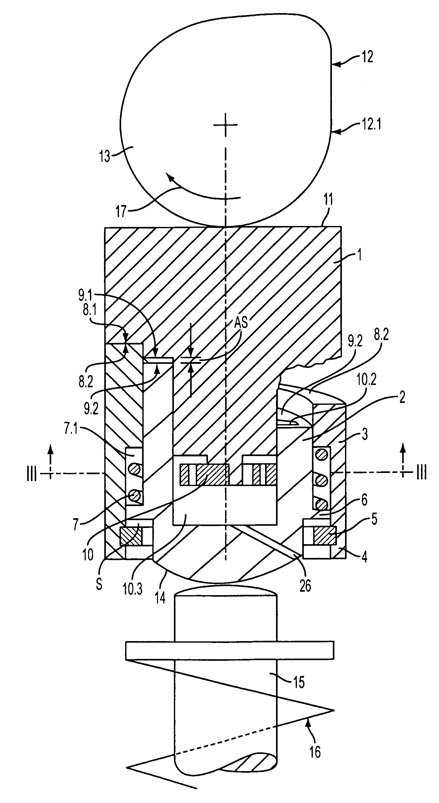
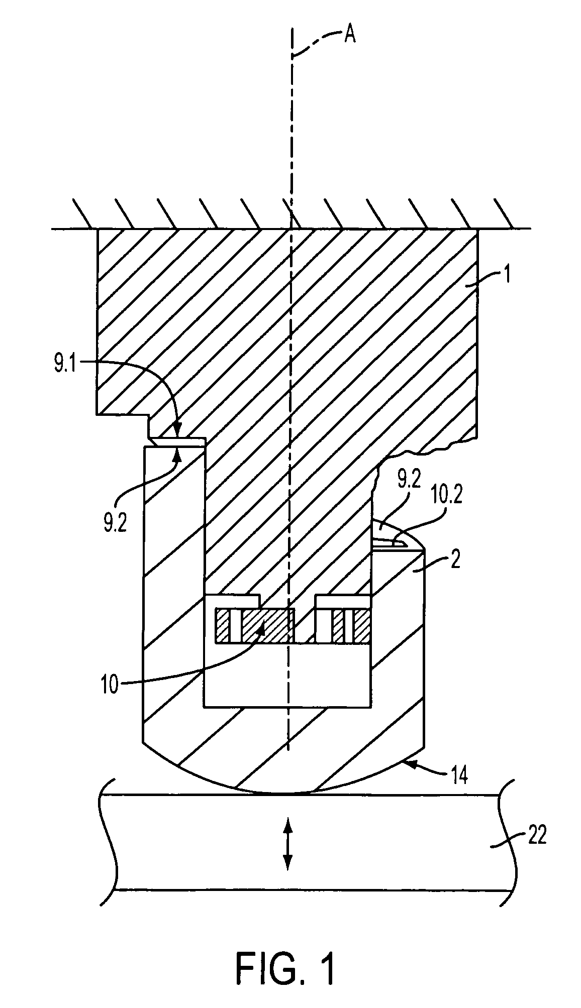
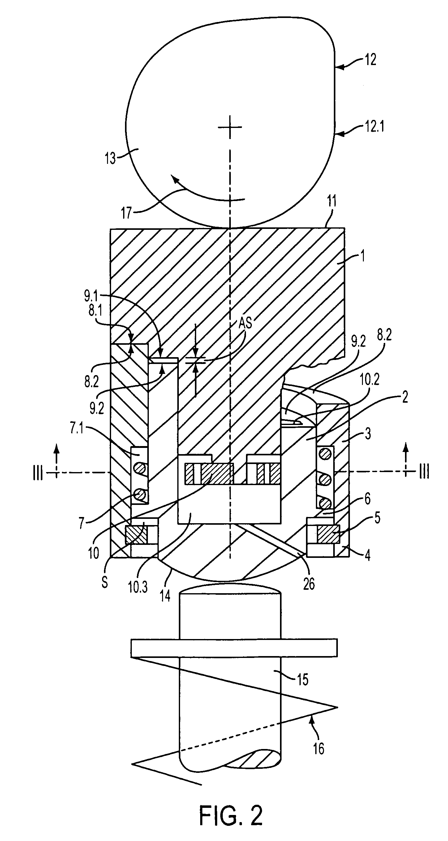
[0027]The schematic illustration of an exemplary embodiment of a mechanical valve play compensation element in FIG. 1 shows a first pressure part 1, embodied for instance in the form of a die or piston, which is axially displaceable relative to a second pressure part 2 and is retained rotatably about the displacement axis A and is embodied as cup-shaped or cylindrical, for instance. The pressure part 2 is braced by its free end 14, for instance on a drag lever 22 to be actuated. The first pressure part 1 is kept stationary, or is connected to a valve drive, depending on the intended use.

[0028]The first pressure part 1 is provided, on its side oriented toward the second pressure part 2, with a helical surface 9.1, with which a corresponding helical surface 9.2 on the second pressure part 2 is associated. The associated helical surfaces form a pair 9 of helical surfaces. Of the helical surfaces 9.1 and 9.2 of the pair 9 of helical surfaces, at least one helical surface is embodied as ...


PUM


Abstract

The invention relates to a mechanical valve play compensation element for a valve drive on a piston combustion engine, comprising a first pressure part (1) which is axially displaceable in relation to a second pressure part (2) and which is fixed in such a way that it can turn about the axis of displacement; a torsion spring element (10) which acts between the first pressure part (1) and the second pressure part (2) and is axially flexible at least to a certain extent; and at least one helical surface (9.1) on the first pressure part (1), to which a corresponding helical surface (9.2) on the second pressure part (2) is allocated, these forming a pair of helical surfaces (9). The surfaces of the helical surface pair (9) are configured as a rough surface and are pressed against each other by the torsion spring element (10).

Description

CROSS REFERENCE TO RELATED APPLICATION[0001]This application is a continuation of application Ser. No. 10 / 181,222, filed Oct. 2, 2002 now U.S. Pat. No. 6,834,628.BACKGROUND OF THE INVENTION[0002]The invention relates to a method for determining the reducing agent concentration (NH3) in the exhaust-gas flow of an internal combustion engine.[0003]In piston combustion engines, it is necessary, between the shaft end of the gas exchange valve on the one hand and the valve drive (cam of the camshaft, valve actuating lever, or the like) acting on it on the other, to dispose a valve play compensation element in order to compensate for temperature-caused changes in the length of the valve shaft and changes, caused by wear to the valve seat, in the height of the shaft end when the gas exchange valve is closed, relative to the valve drive. To that end, a hydraulic valve play compensation element is used, which essentially comprises a cup-shaped cylinder and a piston guided in it; the cylinder ...

Claims


Application Information

Patent Timeline
IPC IPC(8): F01L1/14F01L1/22
CPCF01L1/22
Inventor DUESMANN, MARKUS
Owner FEV MOTORENTECHN
Why Eureka
Try Eureka