Gas-powered tip-jet-driven tilt-rotor compound VTOL aircraft

a technology of tilt-rotor and compound, which is applied in the direction of vertical landing/taking-off aircraft, machines/engines, liquid fuel engines, etc., can solve the problems of achieve the effects of less expensive, easy to take over the powering of both rotors, and saving huge weight, cost and complexity

Active Publication Date: 2006-12-12
FLANIGAN KENNETH WARREN
View PDF2 Cites 119 Cited by
  • Summary
  • Abstract
  • Description
  • Claims
  • Application Information

AI Technical Summary

Benefits of technology

[0009]By utilizing the gas-powered tip-jet driven rotor concept, we transform the tilt-rotor aircraft from a heavy, very complex, very expensive aircraft into an efficient, fast, relatively simple, much less expensive aircraft. Engines can come inboard (perhaps beneath the wing roots), thus saving huge amounts in weight, cost and complexity. In one embodiment, compressed gas from the engines is ducted through each supporting structure or yoke, into the rotor hubs for distribution into the blades and out the tip-jets. Thrust in forward flight is obtained from any combination of thrust from the tip-jet driven rotors and jet exhaust directly from the engines. One engine can easily take over the powering of both rotors with simple valve transfers within the lightweight manifold. Because tip-jet powered rotors are really multiple-flow thrust generators of a superior kind, very large thrust augmentation ratio is achieved.

Problems solved by technology

Engines can come inboard (perhaps beneath the wing roots), thus saving huge amounts in weight, cost and complexity.

Method used


Image

  • Gas-powered tip-jet-driven tilt-rotor compound VTOL aircraft
  • Gas-powered tip-jet-driven tilt-rotor compound VTOL aircraft
  • Gas-powered tip-jet-driven tilt-rotor compound VTOL aircraft

Examples


Embodiment Construction

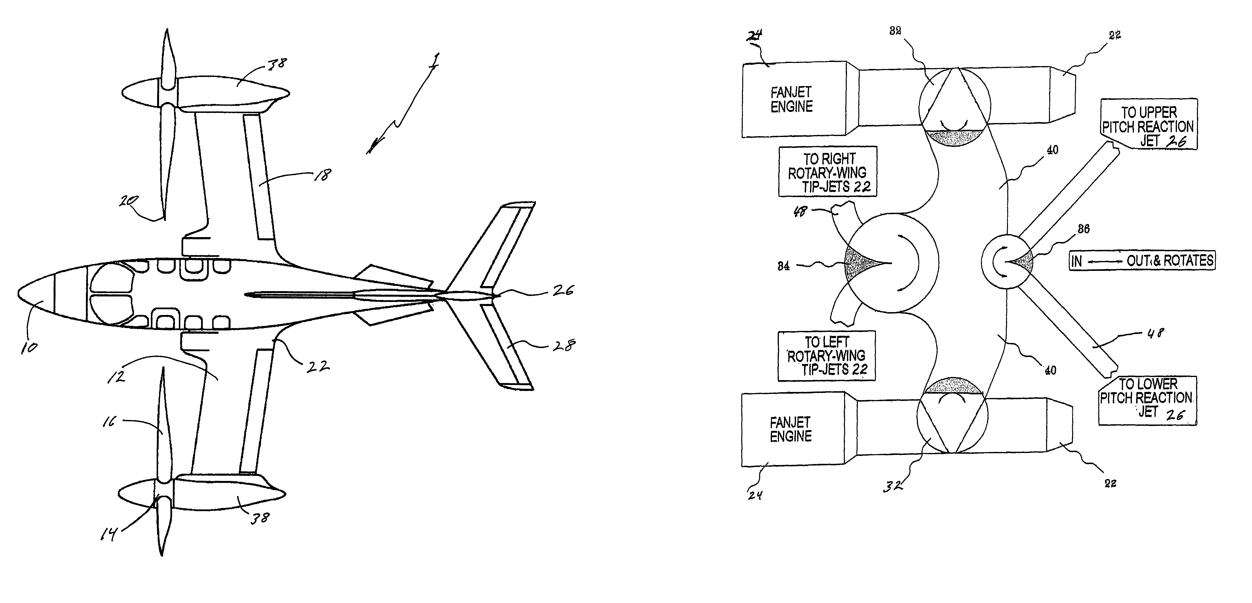
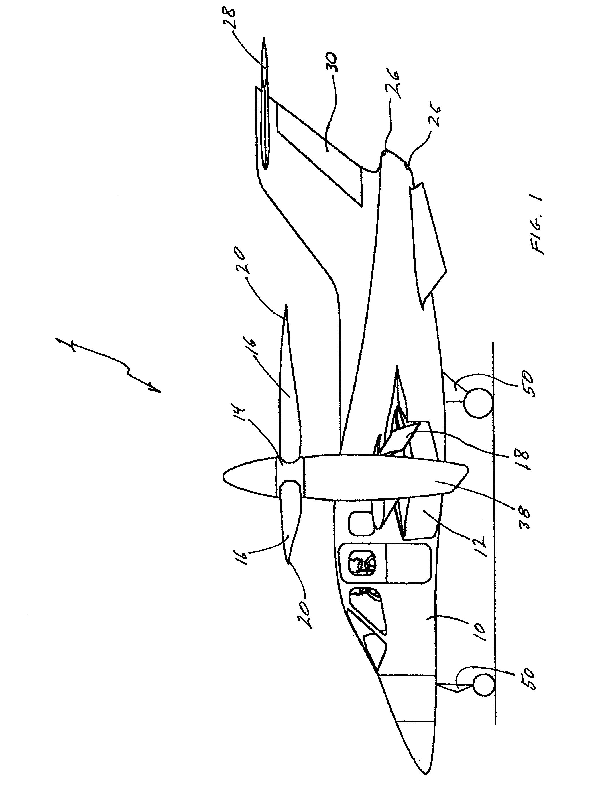
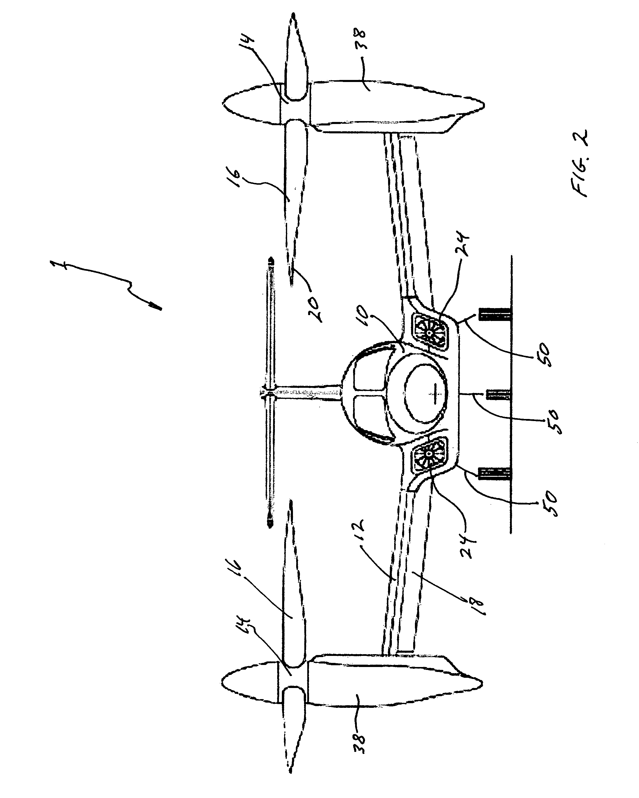
[0023]It is generally understood and defined herein that a compound aircraft is one that has both fixed wings and rotary wings for sustenance of flight. This embodiment of a compound aircraft concerns itself with a particular type of tip-jet driven compound aircraft, and that type is a tilt-rotor tip-jet driven VTOL aircraft. As we shall see momentarily in the drawings, the invention comprises a supporting structure, hub, rotor / propeller (hereinafter called rotor assembly) and nozzles or tip-jets (as fully described in my first disclosure). The supporting structure for multi-engine aircraft (or yoke for single engine aircraft) is rotated about the pitch axis that is generally coincident with the center of lift and / or the center of gravity in the case of single engine aircraft. The yoke or supporting structure extends up in the vertical position to put the rotor or propeller in the horizontal plane for vertical take-offs and landings, and then is rotated to the horizontal position, w...


PUM


Abstract

A tilt-rotor compound VTOL aircraft has a multiple-flow thrust generator(s) comprising a gas-powered tip-jet driven rotor(s) having a thrust-augmentation ratio of at least two; that tilts about the aircraft's pitch axis wherein the rotor's plane of rotation is substantially horizontal for VTOL operations and the rotor's plane of rotation is substantially vertical forward flight operations. A relatively small fixed-wing sustains the aircraft during forward flight. Compressed exhaust gas from the fan-jet engine(s) is ducted to a manifold having valves which control power to the multiple-flow thrust generator(s) and to the jet exhaust nozzle(s) as supplemental thrust for forward propulsion and yaw control. The manifold also serves to distribute compressed gas to the dead engine side of the aircraft in the event of a dead engine emergency, and to reaction jets for attitude control during VTOL operations. Thus this tilt-rotor aircraft is more efficient, faster, immensely lighter, less complex and less expensive to purchase and maintain than its shaft-driven counterparts.

Description

CROSS-REFERENCE TO RELATED APPLICATIONCLAIM OF PRIORITY[0001]This application claims the benefit of Provisional Application Ser. Nos. 60 / 547,025, filed 2004, Feb. 23 by the present inventor.BACKGROUND OF INVENTION—FIELD OF INVENTION[0002]This invention relates to tilt-rotor compound VTOL aircraft that utilize compressed gas driven tilt-rotors.BACKGROUND OF INVENTION[0003]In around the year 100 BC, Hero of Alexandria discovered the reaction engine with his aeolipile experiment. Then the Wright brothers introduced powered flight in 1903, and in 1910 Henri Marie Coanda married the two together to fly the first jet-propelled airplane. In 1955 the Bell XV-3, the world's first tilt-rotor aircraft, made its first flight, and in the same year the McDonnell XV-1 tip-jet autogyro made its record-breaking flight.[0004]With man's desire for aircraft that would use less runway coincident with flying faster, safer and easier handling, he has created many different types of VTOL or SVTOL aircraft ...

Claims


Application Information

Patent Timeline
Patent Type & Authority Patents(United States)
IPC IPC(8): B64C27/22
CPCB64C29/0033
Inventor FLANIGAN, KENNETH WARREN
Owner FLANIGAN KENNETH WARREN
Why Eureka
Try Eureka