
Head performance based nano-machining process control for stripe forming of advanced sliders

a nano-machining and process control technology, applied in the field of stripe forming process, can solve the problems of insufficient process control schemes using elgs and a holder capable of bending the bar, and achieve the effect of improving the control scheme and improving the quality of the holder

Inactive Publication Date: 2006-12-12
SEAGATE TECH LLC
View PDF18 Cites 10 Cited by
  • Summary
  • Abstract
  • Description
  • Claims
  • Application Information

AI Technical Summary

Benefits of technology

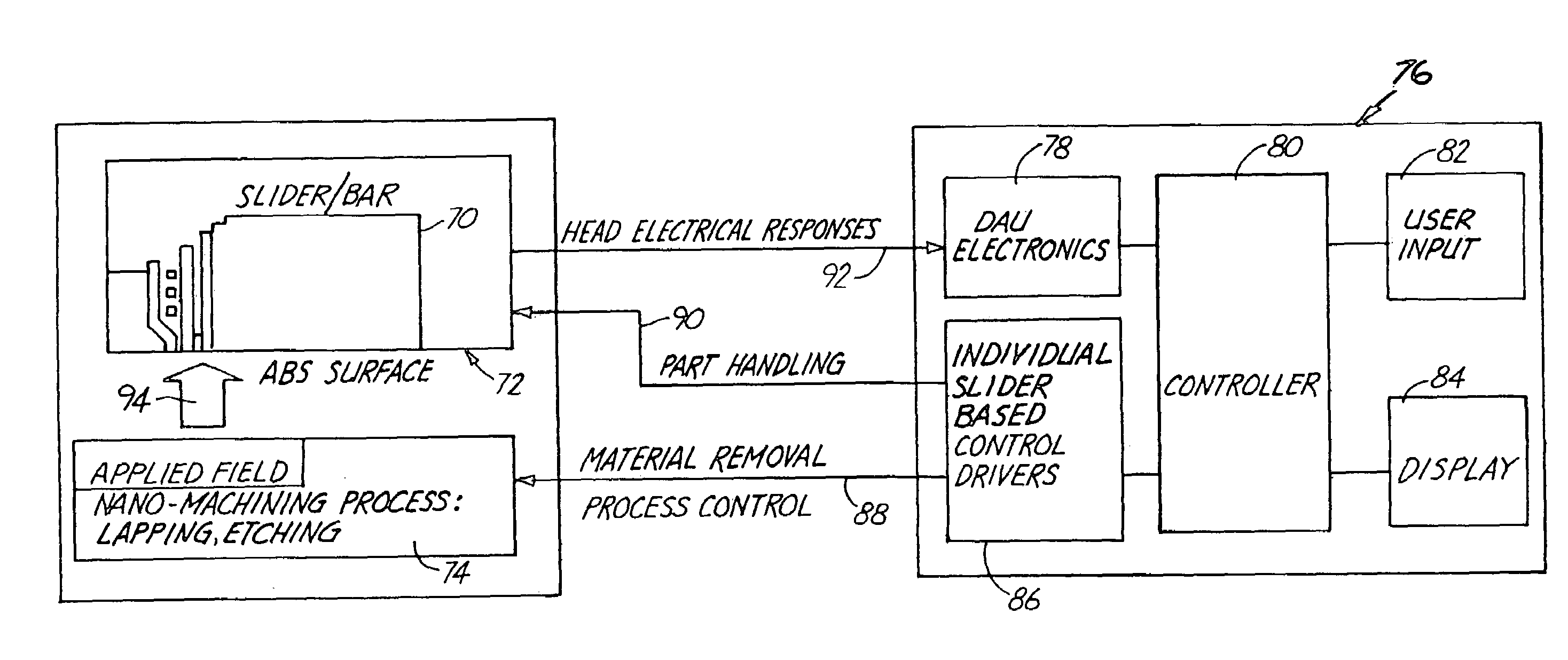
[0010]The present invention is a method of using direct head electrical response signals for feedback process control, rather than indirect parameters previously collected from ELGs. When lapping the air bearing surface of a bar of sliders, a magnetic field is applied to the air bearing surface and a bias current is applied to the reader elements. A head electrical response, such as amplitude or re

Problems solved by technology

The existing process control schemes using ELGs and a holder capable of bending the bar are often inadequate for achieving the desired stripe height for each slider on the bar within the tolerance required at such small dimensions.

Method used


Image

  • Head performance based nano-machining process control for stripe forming of advanced sliders
  • Head performance based nano-machining process control for stripe forming of advanced sliders
  • Head performance based nano-machining process control for stripe forming of advanced sliders

Examples


Embodiment Construction

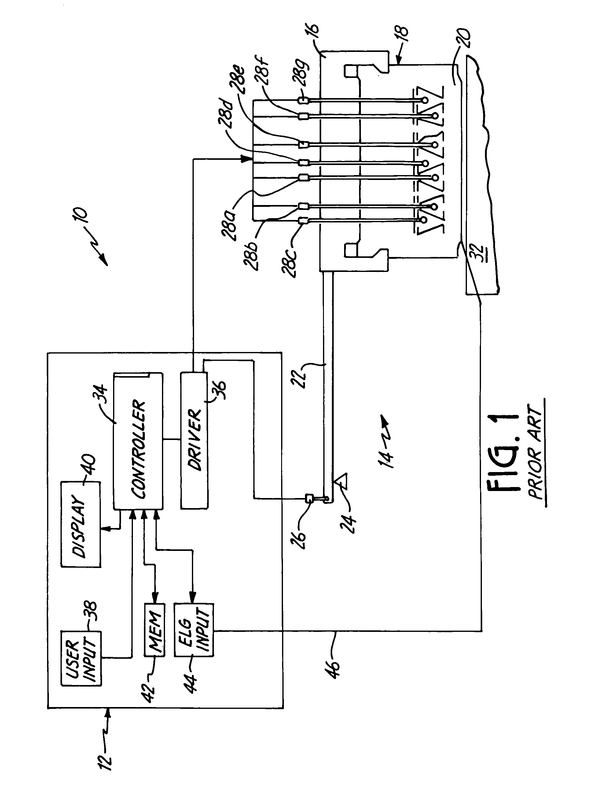
[0017]FIG. 1 is a simplified diagram of a prior art lapping system. The lapping system 10 comprises a control system 12 and lapping mechanism 14. The lapping mechanism 14 comprises a fixture 16 holding a carrier 18 to which is mounted a bar 20. Attached to the fixture 16 is an elongated arm 22 which is coupled to a fulcrum 24. Also attached to the arm 22 is a balancing actuator 26 which is positioned opposite the carrier 18 relative to the fulcrum 24. Located on the fixture 16 are several actuators 28a through 28g which are configured to manipulate the bar 20 such that parts of the bar 20 can be brought into contact or removed from contacting a lapping surface 32.

[0018]The control system comprises a controller 34 and driver 36. Also included as part of the control system 12 is a user input 38 and a display 40. The controller may further include a memory 42. Finally, an ELG input 44 further comprises the part of the control system 12. The controller 34 directs the driver 36 to actuat...


PUM

PropertyMeasurementUnit
Magnetic fieldaaaaaaaaaa
Electrical resistanceaaaaaaaaaa
Heightaaaaaaaaaa

Abstract

The present invention is a method of using direct head electrical response signals for feedback process control. When lapping the air bearing surface of a bar of sliders, a magnetic field is applied to the air bearing surface and a bias current is applied to the reader elements. A head electrical response, such as amplitude or resistance change, is measured and is used to control the lapping device. Using a fixture which allows individual slider machining, a controller can be used to monitor the head response signal for each slider on the bar and individually control each slider on the bar so that material removal over each slider proceeds until a predetermined target stripe height is reached.

Description

CROSS-REFERENCE TO RELATED APPLICATION(S)[0001]This application claims priority from Provisional Application No. 60 / 223,927, filed on Aug. 9, 2000, for “Head Performance Based Nano-machining Process Control for Stripe Forming of Advanced Sliders” by Shanlin Hao, Jeffery K. Berkowitz, and Peter R. Goglia. Provisional Application No. 60 / 223,927 is incorporated herein by reference.BACKGROUND OF THE INVENTION[0002]The present invention relates to the batch fabrication of magnetic read / write transducers, and in particular to a stripe forming process which machines the transducer to a specific stripe height target.[0003]Magnetic read / write transducers or sliders are typically produced by using thin film deposition techniques. In a typical process, an array of sliders are formed on a common substrate or wafer. As part of the formation of the sliders, electric lapping guides (ELGs) are also formed on the wafer, along with bond pads and electrical connections which allow for inspecting and t...

Claims


Application Information

Patent Timeline
IPC IPC(8): B24B49/10
CPCB24B37/00B24B37/048B24B49/10B24B41/06Y10T29/49046
Inventor HAO, SHANLINBERKOWITZ, JEFFERY K.GOGLIA, PETER R.
Owner SEAGATE TECH LLC
Learn More