

Balloon catheter for multiple adjustable stent deployment
a balloon catheter and adjustable technology, applied in the field of balloon catheters, can solve the problems of increasing the chance of damaging a blood vessel, prolonging the duration of the procedure, and causing a lot of discomfort for patients
- Summary
- Abstract
- Description
- Claims
- Application Information
AI Technical Summary
Benefits of technology
Problems solved by technology
Method used
Image

Examples
example i
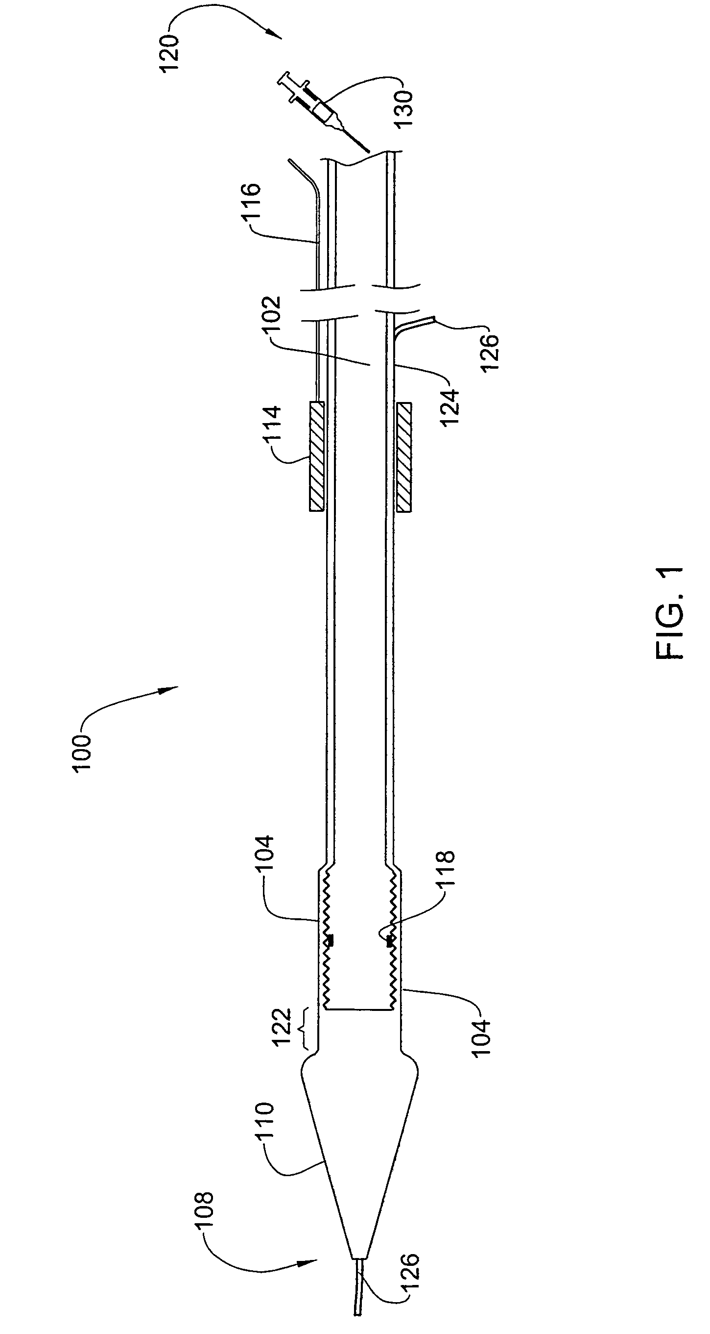
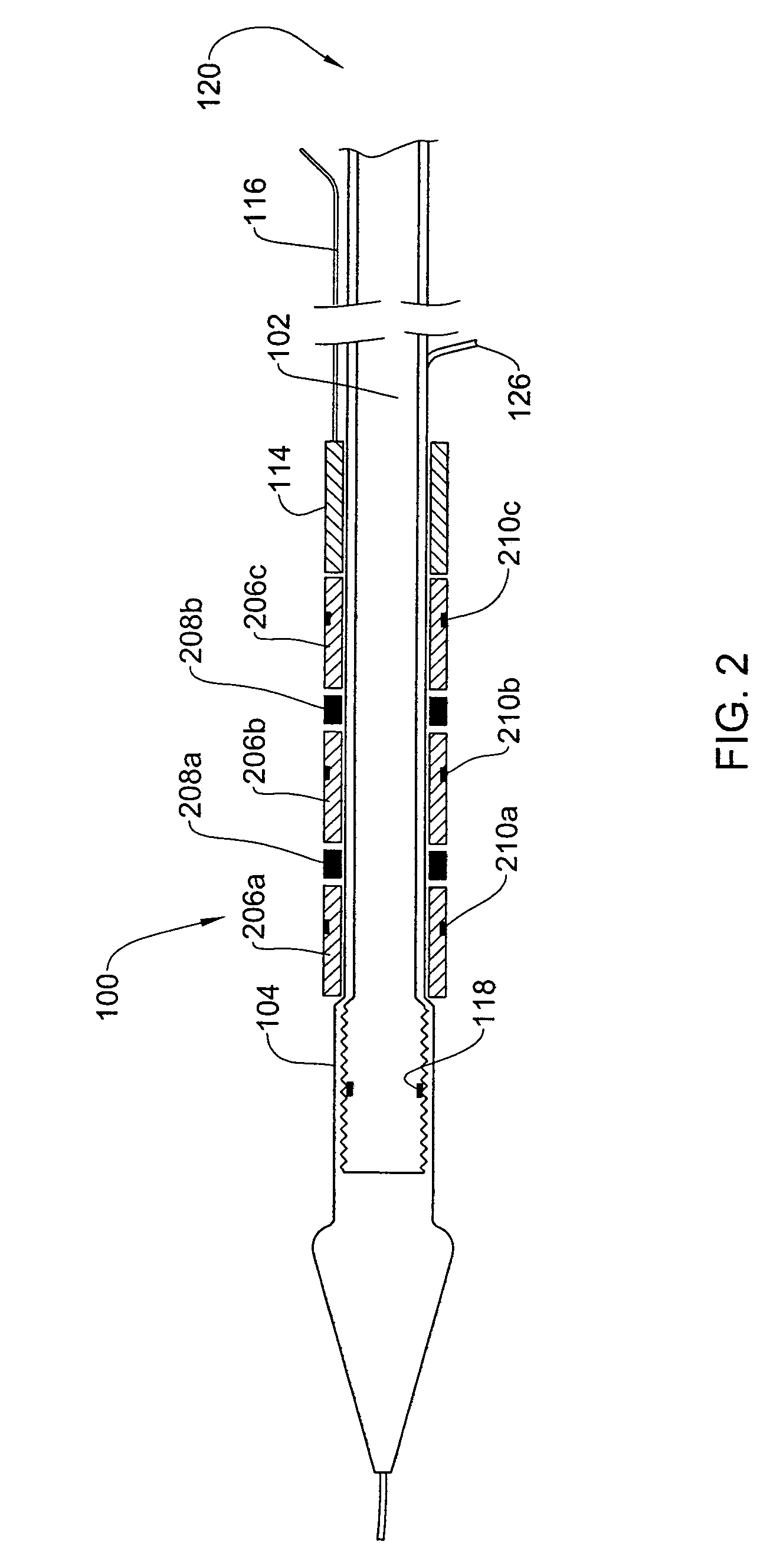
[0030]FIG. 1 shows a catheter 100 for deploying stents in accordance with one embodiment of the invention. The catheter 100 has a distal end 108 and a proximal end 120. The catheter 100 comprises a flexible tube 102, which is connected to an inflatable balloon 104 proximate to its distal end. The balloon 104 is shown in the Figure in its deflated state. A radio-opaque marker 118 is located on the balloon wall. The catheter 100 has at its distal end 108 a tapered tip 110 that may be inserted into a stenosis in order to open the stenosis. A syringe 130 may be used to introduce a fluid into the tube 102 in order to inflate the balloon 104 as described in detail below.
[0031]A longitudinal shaft 124 in the wall of the tube 102 is configured to receive a guidewire 126 used in navigating the catheter in the vascular system. A neck region 122 of the tube 102 intervenes between the distal end of the balloon 104 and the tip 110. The proximal end of the tip 110 is broadened to form a shoulder ...
example ii
[0038]FIG. 6 shows a catheter 600 for deploying stents in accordance with another embodiment of the invention. The embodiment of FIG. 6 has many components in common with the embodiment of FIG. 1, and similar components are identified by the same reference numeral in both embodiments.
[0039]The embodiment of FIG. 6 has a cylindrical carriage 605 mounted on the tube 102. The carriage has a plurality of annular depressions (three are shown in FIG. 6) 610a, 610b and 610c configured to receive a stent as described below. The depressions 610 all have the same length A as indicated in FIG. 6, which is essentially equal to the length of the balloon 104. Between the depressions 610 are barriers 620a and 620b. The carriage 605 is made from an elastic material such as rubber. The carriage 605 is slidable along the tube 102 by means of a wire 116 that extends along the length of the tube 102 from the proximal end 120 of the catheter to the carriage 605. The carriage 605 and the wire 116 form a ...
example iii
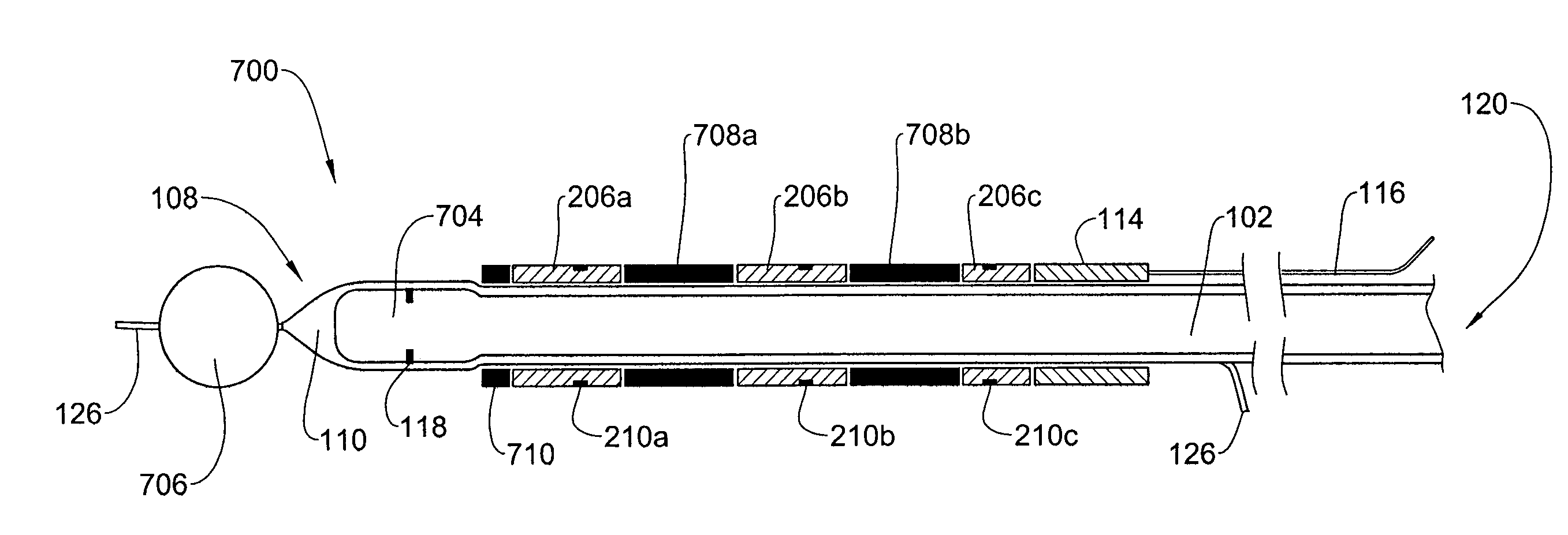
[0045]This example illustrates an embodiment which is an improvement over the embodiment described in Example I. With reference to FIG. 11, there is shown a catheter 700 having a distal end 108 and a proximal end 120. As in FIG. 1, the catheter 700 comprises a flexible tube 102, which is connected to an inflatable balloon 704 proximate to its distal end. A radio-opaque marker 118 is located on the balloon wall. The catheter 700 has at its distal end 108 a tapered tip 110, but unlike in Example I, there is no neck region, and the tip is not enlarged. The balloon in this embodiment may be a conventional inflatable balloon used in balloon angioplasty.
[0046]As in Example I, a guidewire 126 extends along the tube 102, exiting at the distal end 108 of the catheter. An anterior positioner in the form of a perforated sphere 706 is fixed to the guidewire anterior to the balloon 704, e.g. the guidewire passes through a bore channel extending through the sphere. The diameter of the sphere is s...
PUM
 Abstract
Description
Claims
Application Information