Signal readout structure for an image sensing apparatus

a signal readout and image sensing technology, applied in the direction of television system, television system scanning details, radioation controlled devices, etc., can solve the problems of complicating downstream signal processing circuit structure for operations, two colors will mix, and increase the number of output pins, etc., to achieve the effect of simple structure and superior picture quality

Inactive Publication Date: 2006-12-12
CANON KK
View PDF17 Cites 26 Cited by
  • Summary
  • Abstract
  • Description
  • Claims
  • Application Information

AI Technical Summary

Benefits of technology

[0024]Accordingly, the present invention has been made in consideration of the above-described situation, and has as its object to output signals of all colors at high speed from a color image sensing apparatus as well as form an image of superior picture quality which avoids color mixing even when multiplexing signals from multiple output systems at high speed with a comparatively simple structure, while holding the number of output pins to a minimum.

Problems solved by technology

However, Japanese Laid-Open Patent Application No. 9-46480 and 2001-245221 have a disadvantage in that they increase the number of output pins because four or five output pins are required for each output terminal.
However, by outputting signals of different colors from a single output terminal using such multiplexing as described above, there is a risk that the two colors will mix, and in any case such an arrangement complicates downstream signal processing circuit structures for operations such as signal separation outside semiconductor image sensing apparatuses.

Method used


Image

  • Signal readout structure for an image sensing apparatus
  • Signal readout structure for an image sensing apparatus
  • Signal readout structure for an image sensing apparatus

Examples


first embodiment

(First Embodiment)

[0042]A description is now given of the first embodiment of the present invention, with reference to FIGS. 1 and 2.

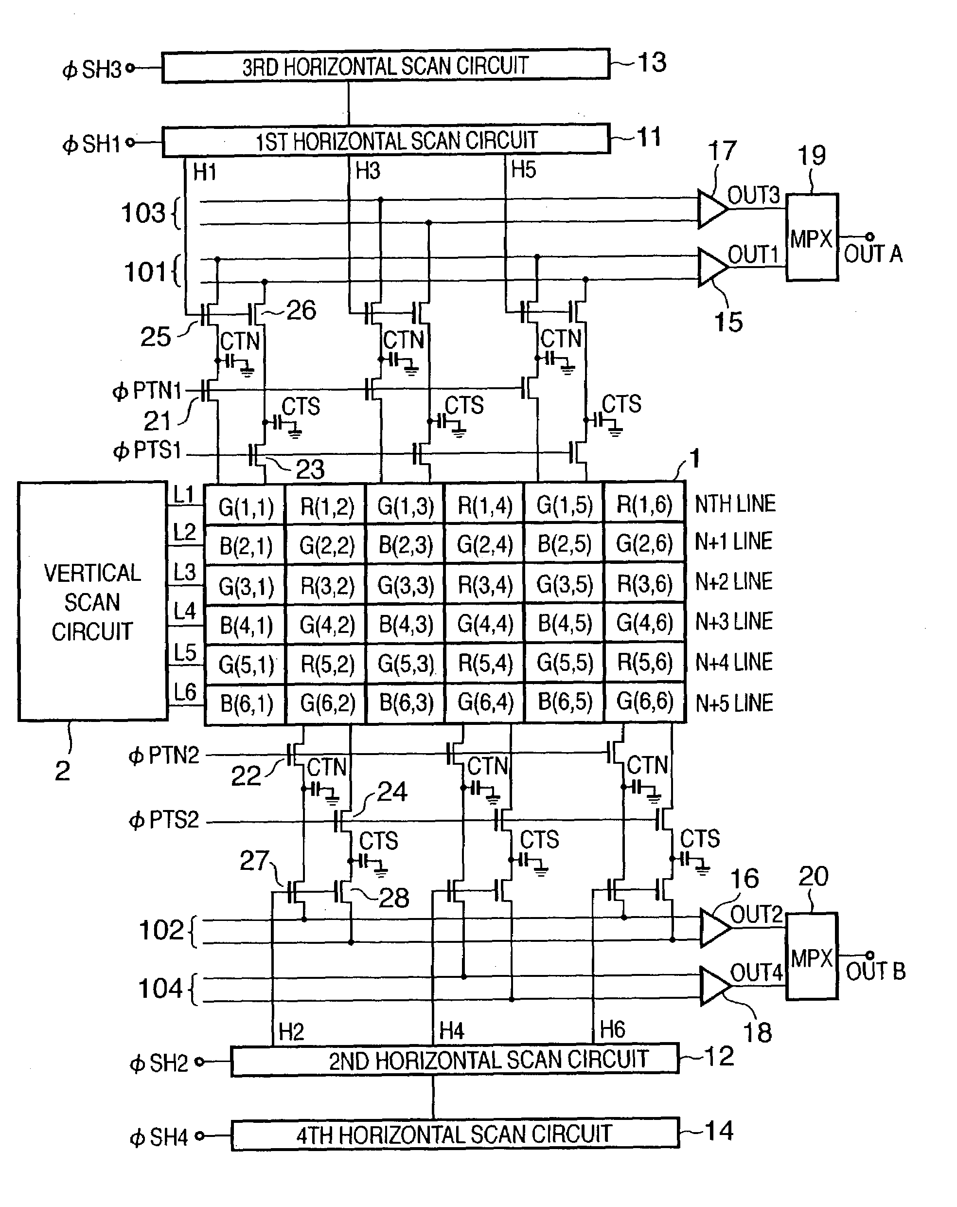
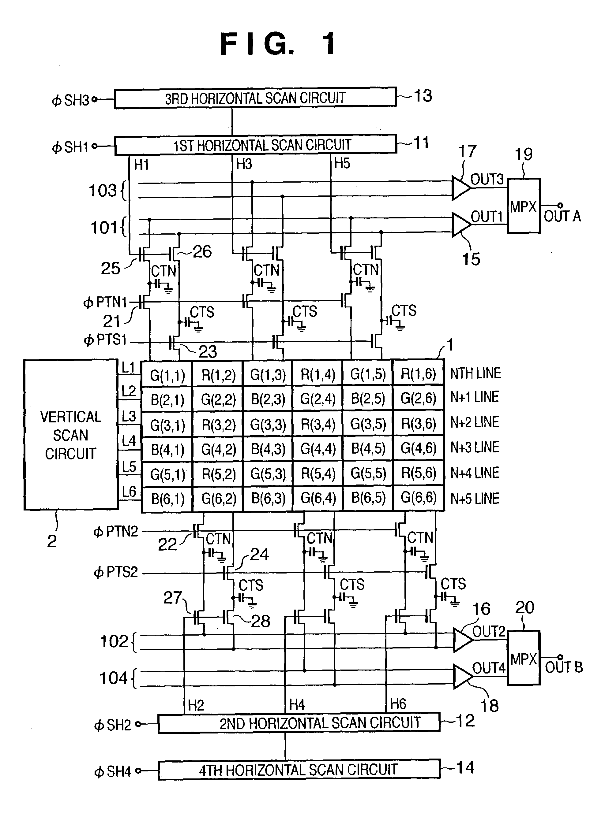
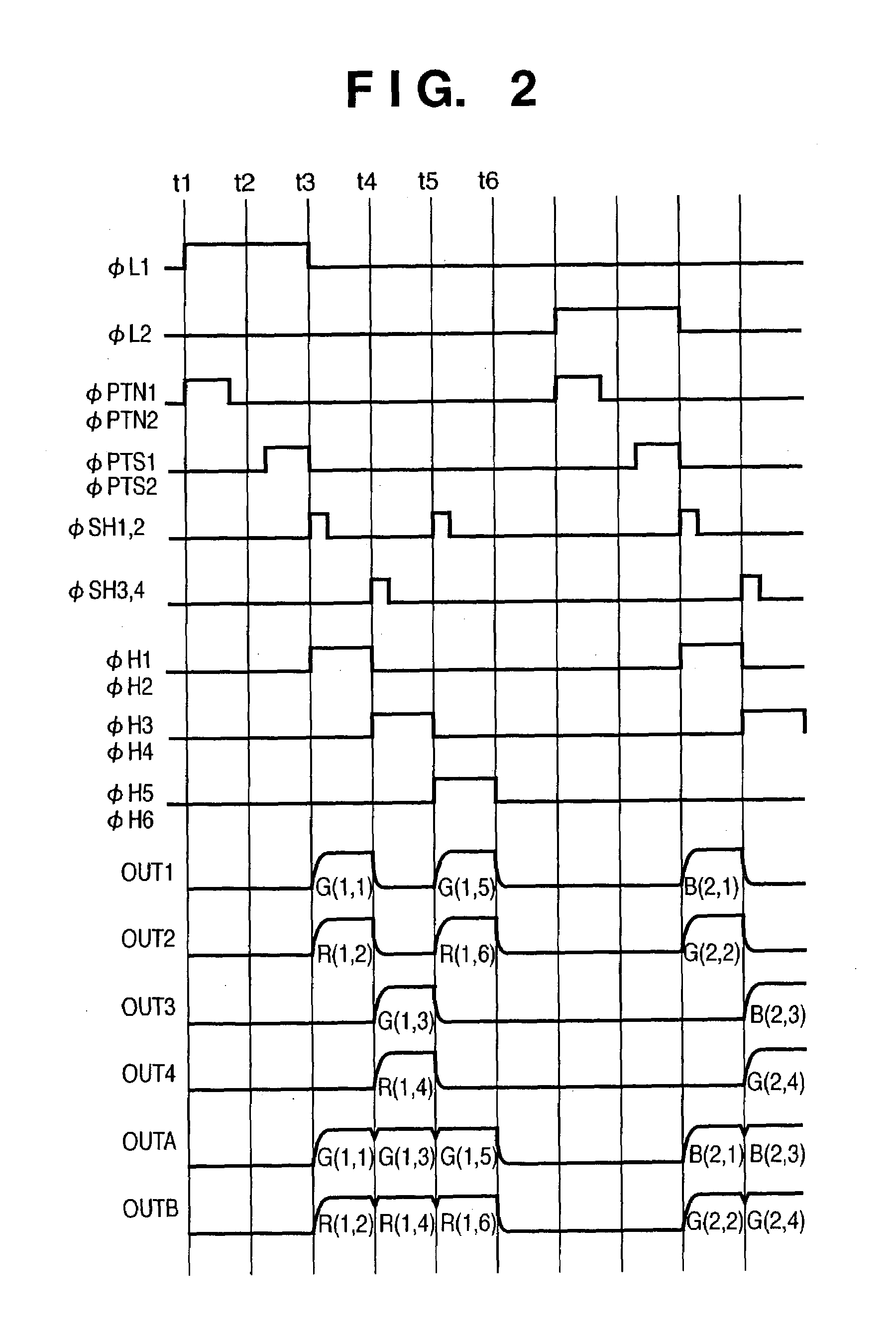
[0043]FIG. 1 is a diagram of the structure of an image sensing apparatus according to a first embodiment of the present invention. FIG. 2 is a timing chart showing the drive timing and output signals of the image sensing apparatus of FIG. 1.

[0044]In FIG. 1, reference numeral 1 denotes a pixel having a Bayer arrangement color filter. The numbers inside the parentheses next to the color designations R (red), G (green) and B (blue), are the pixel coordinates. It should be noted that, for simplicity of description, the present example uses a 6×6 arrangement of pixels, but in fact an extremely large number of pixels are arrayed in an actual arrangement.

[0045]The pixels 1 are each connected to line selection lines L1–L6 at each line, with the line selection lines L1–L6 being turned HIGH (hereinafter H) in sequence by line selection signals supplied from the ...

second embodiment

(Second Embodiment)

[0054]A description will now be given of the second embodiment of the present invention, with reference to the accompanying drawings.

[0055]It should be noted that, in order to simplify the explanation, a description of the drive method and noise deletion method is omitted for the second and all subsequent embodiments of the present invention described herein below.

[0056]FIG. 3 is a diagram of the structure of an image sensing apparatus according to a second embodiment of the present invention. FIG. 4 is a timing chart showing the drive timing and output signals of the image sensing apparatus of FIG. 3. As can be seen in FIG. 3, in the second embodiment, the first and third horizontal scan circuits 11 and 13 of the first embodiment shown in FIG. 1, as well as the second and fourth horizontal scan circuits 12 and 14 also shown in FIG. 1, have each been replaced with a single horizontal scan circuit. It should be noted that, in FIG. 3, structures that are the same as...

third embodiment

(Third Embodiment)

[0059]A description will now be given of a third embodiment of the present invention, with reference to the accompanying drawings.

[0060]FIG. 5 is a schematic diagram of the structure of an image sensing apparatus according to a third embodiment of the present invention. FIG. 5 shows an arrangement in which the signal lines 101–104 depicted in FIG. 1 and FIG. 3 output to left and right lateral directions from a center thereof. It should be noted that, in FIG. 5, structures that are identical to those shown in FIGS. 1 and 3 are given identical reference numerals, and structures equivalent to those shown in FIGS. 1 and 3 but divided into lateral arrangements are given reference numerals followed by the reference symbol R (right) or L (left), as appropriate. Also, as can be appreciated by those of ordinary skill in the art, the structure shown in FIG. 5 can be easily adapted to the image sensing apparatus of the first embodiment described above.


PUM


Abstract

An image sensing apparatus includes a photoelectric converter having a plurality of pixels covered by a color filter composed of a plurality of colors, a plurality of common readout units adapted to sequentially output signals from the plurality of pixels, a time division multiplex (TDM) unit for time division multiplexing signals from the plurality of common readout units, and a readout control unit for reading the signals from the plurality of pixels to the common readout units in such a way that signals from pixels covered by color filters of the same color are continuously multiplexed.

Description

FIELD OF THE INVENTION[0001]The present invention relates to an image sensing apparatus, and more particularly, to a signal readout structure for an image sensing apparatus.BACKGROUND OF THE INVENTION[0002]Recent technical advances in digital still cameras, digital video cameras and other such image input devices have tended to provide sensors with more and more picture elements (hereinafter pixels) in order to further improve the quality of the images formed, with the result that higher readout speeds are required as well. In order to meet such a need, a readout method has been developed by which the pixel signals have been divided into a plurality of readout channels. A description of this conventional method is now given with reference to FIGS. 11 and 12.[0003]FIG. 11 is a diagram of the structure of a conventional image sensing apparatus. FIG. 12 is a timing chart showing the drive timing and output signals of a conventional image sensing apparatus.[0004]The image sensing appara...

Claims


Application Information

Patent Timeline
Patent Type & Authority Patents(United States)
IPC IPC(8): H04N3/14H04N5/335H04N9/04H04N9/083H01L27/146H04N5/341H04N5/365H04N5/369H04N5/378H04N9/07
CPCH04N3/1575H04N9/045H04N25/767
Inventor OGURA, MASANORIINUI, FUMIHIROITANO, TETSUYA
Owner CANON KK
Why Eureka
Try Eureka