
Finless training projectile with improved flight stability over an extended range

a projectile and flight stability technology, applied in the field of training munitions, can solve the problems of less energy, less economical propellant use, training cost, etc., and achieve the effects of low cost, high performance and high stability

Inactive Publication Date: 2006-12-19
UNITED STATES OF AMERICA THE AS REPRESENTED BY THE SEC OF THE ARMY
View PDF7 Cites 8 Cited by
  • Summary
  • Abstract
  • Description
  • Claims
  • Application Information

AI Technical Summary

Benefits of technology

[0006]The finless training projectile provides high performance at low cost for use in training exercises. Although conventional spike-nose training projectiles have proven to be satisfactory for their intended purpose, the present finless training projectile provides a higher stability throughout its flight regime.
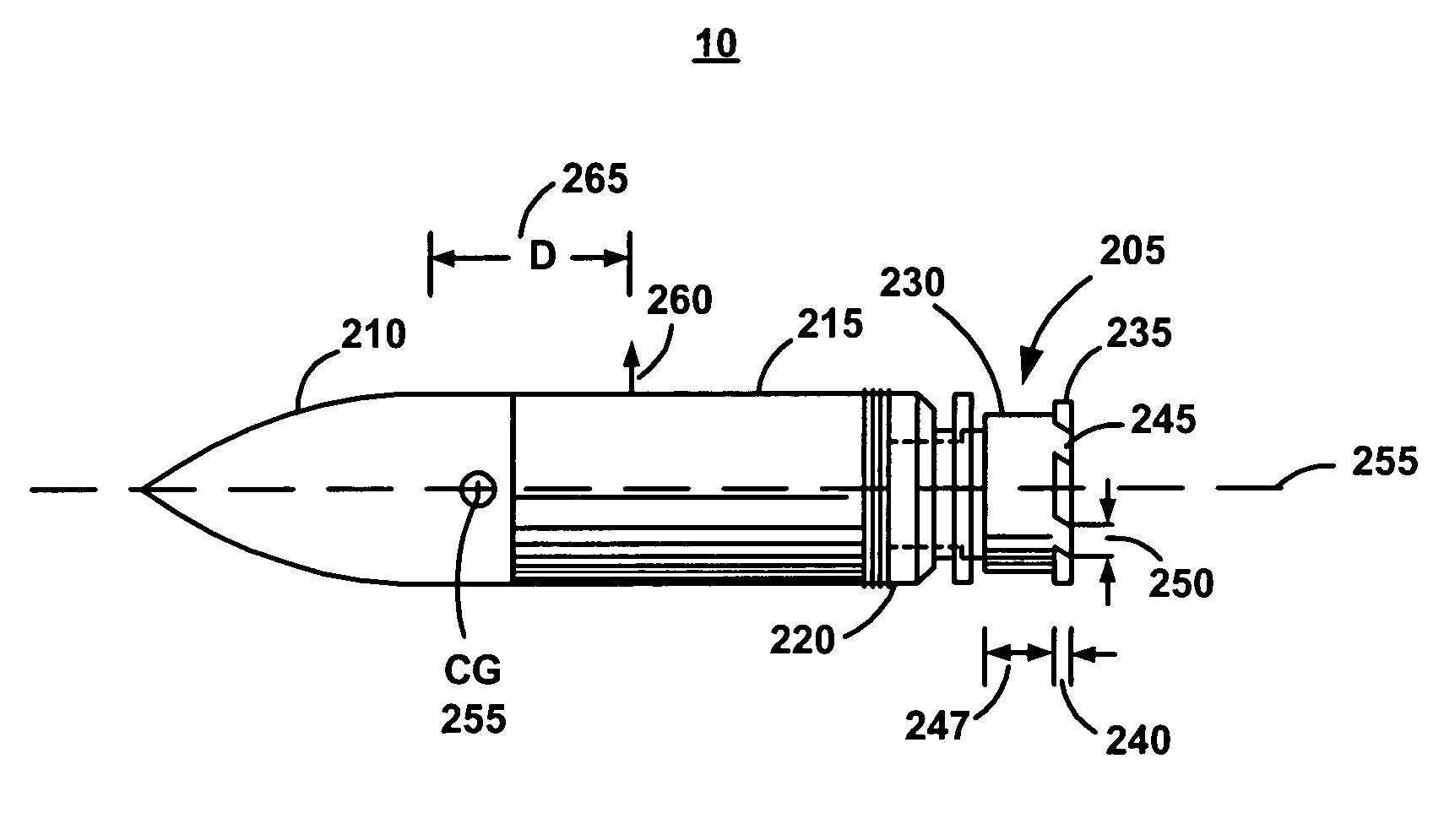
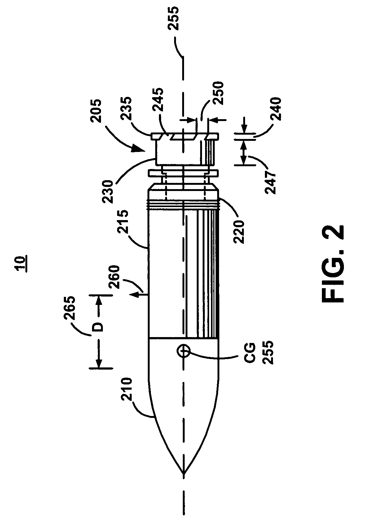
[0007]More specifically, the finless training projectile maintains a higher static margin than the conventional spike-nose training projectile due to the following two improvements. The first being that the center of gravity for the flight projectile has been moved further forward. The second is that the center of pressure remains in a constant rearward position, throughout the Mach number range encountered during flight. This combination of physical features provides greater flight stability for enhanced target accuracy.
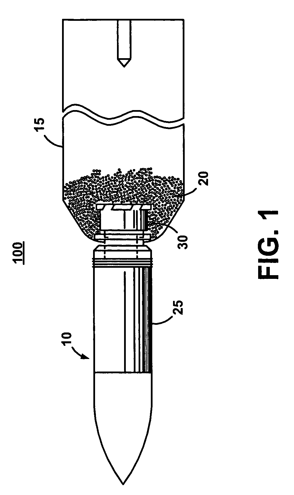
[0008]Propellant for training projectiles is provided in a cartridge attached to a base of the training cartridge. Any fins or other flight stabilizing features on the base of training projectiles intrude into the cartridge. The finless, cone-nosed training projectile requires relatively little space in the cartridge, freeing up space in the cartridge for propellant. Consequently, a less energetic, more economical propellant can be used, further reducing training costs and improving performance.

Problems solved by technology

Consequently, a less energetic, more economical propellant can be used, further reducing training costs and improving performance.

Method used


Image

  • Finless training projectile with improved flight stability over an extended range
  • Finless training projectile with improved flight stability over an extended range
  • Finless training projectile with improved flight stability over an extended range

Examples


Embodiment Construction

[0015]FIG. 1 is a cross-sectional diagram of a training cartridge 100 comprising a finless, ogival-nosed training projectile 10 (also referenced herein as projectile 10) according to the present invention. The training cartridge 100 comprises a canister 15 and a propellant 20. The projectile 10 comprises a body 25 and a tail 30.

[0016]FIG. 2 is a diagram of projectile 10. Reference is made to U.S. Pat. No. 005,238,130, which is incorporated herein in its entirety. A stabilizer 205 of the projectile 10 is shown attached to the rearwardmost (tail) end of the projectile 10. Projectile 10 may be, for example a tank round for a 120 mm smooth bore system. Stabilizer 205 ensures that the projectile spins when fired from such a smooth bore or non-rifled system. Projectile 10 possesses a nose forwardmost (front) portion 210 and a rearward or aft cylindrical portion 215 having stabilizer 205 attached thereto. The diameter of cylindrical portion 215 is slightly smaller than the inside diameter ...


PUM


Abstract

A finless cone-nosed, ogival-nosed, or combination ogive-cone nosed training projectile is statically stable, yet has adequate spin rate to compensate for aerodynamic or mass asymmetries. In addition, the training projectile can be fired from smooth bore or rifled cannons of various calibers, including 120 mm and 105 mm. Spin torque and stability augmentation are provided by a radially angled slotted tail flange attached to the rear of the training projectile, providing high performance and improved accuracy at low cost for use in training exercises. The training projectile has a higher static margin than conventional devices, and provides the ability to train personnel with a training projectile that achieves flight ranges similar to its matching tactical projectile, and has improved accuracy.

Description

FEDERAL RESEARCH STATEMENT[0001]The inventions described herein may be manufactured, used and licensed by or for the U.S. Government for U.S. Government purposes.BACKGROUND OF THE INVENTIONFIELD OF THE INVENTION[0002]The present invention generally relates to training munitions for training military personnel. In particular, the present invention relates to a finless training projectile that develops spin in flight from radially angled slots in a slotted tail piece.[0003]The military has many different types of projectiles of tank and artillery rounds. In addition, new projectiles of tank and artillery rounds are continually being developed. For each operating projectile, an identically shaped training cartridge is required for use in training personnel who will use the real or tactical projectile.[0004]The performance of training projectiles should correspond to the matching real or tactical projectile as closely as possible. Conventional training rounds utilize folding or fixed fi...

Claims


Application Information

Patent Timeline
Patent Type & Authority Patents(United States)
IPC IPC(8): F42B10/24
CPCF42B8/12F42B10/26F42B10/38
Inventor GILMAN, STEWARTFARINA, ANTHONYMANOLE, LEON
Owner UNITED STATES OF AMERICA THE AS REPRESENTED BY THE SEC OF THE ARMY
Learn More