Clog resistant drain

a drain and drain technology, applied in water installations, nibs, constructions, etc., can solve the problems of clogging, additional development of unsanitary conditions, clogging of drains, etc., and achieve the effects of simple construction, low cost and clogging of drains

Inactive Publication Date: 2006-12-19
KAMBEYANDA DONA M
View PDF15 Cites 34 Cited by
  • Summary
  • Abstract
  • Description
  • Claims
  • Application Information

AI Technical Summary

Benefits of technology

[0014]It is an object of the present invention to provide a drain straining mechanism that does not restrict the flow of waste water through the drain into the sewer collection piping, while effectively trapping small and larger particles including oils and soap which c...

Problems solved by technology

Drains, such those for kitchen sinks, tubs and showers, clog due to collection of particles suspended in the waste water flow, such as hair.
Alternatively, as the impediments to free flow build, there is an additional development of unsanitary conditions, as soap scum, dirt and related products of bathing and/or kitchen grease being trapped in the drains by the collection of debris because of the inherent reduction of water flow due to the conventional filtering and screening apparatus.
Most existing drains either provide no restriction of usual sloughed waste, allowing build-up to oc...

Method used


Image

  • Clog resistant drain
  • Clog resistant drain
  • Clog resistant drain

Examples


Embodiment Construction

[0023]In the following detailed description of the preferred embodiments, reference is made to the accompanying drawings which form a part hereof, and in which are shown specific embodiments in which the invention may be practiced. It is to be understood that other embodiments may be utilized and structural changes within the skill of the art may be made without departing from the scope of the present invention.

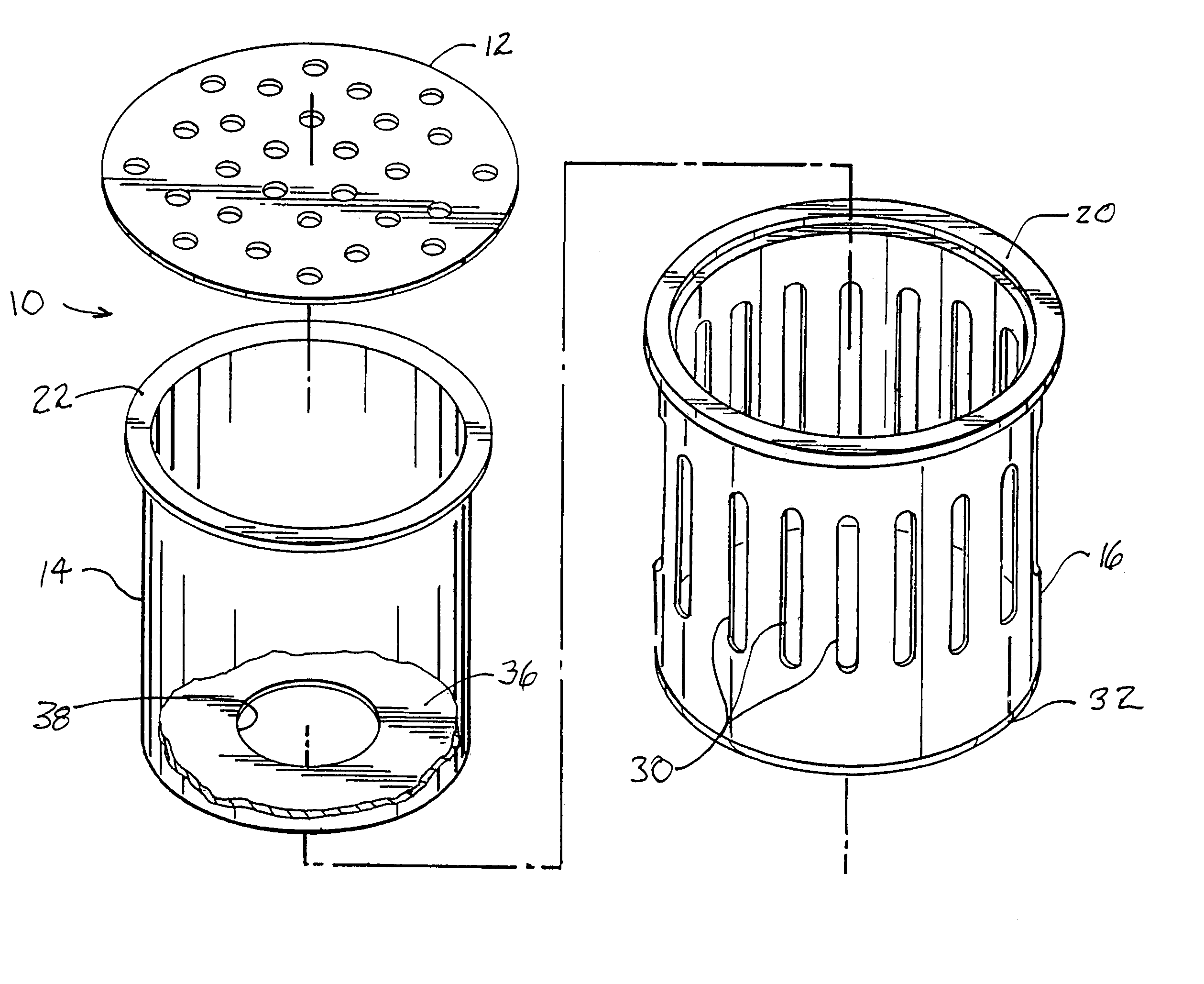
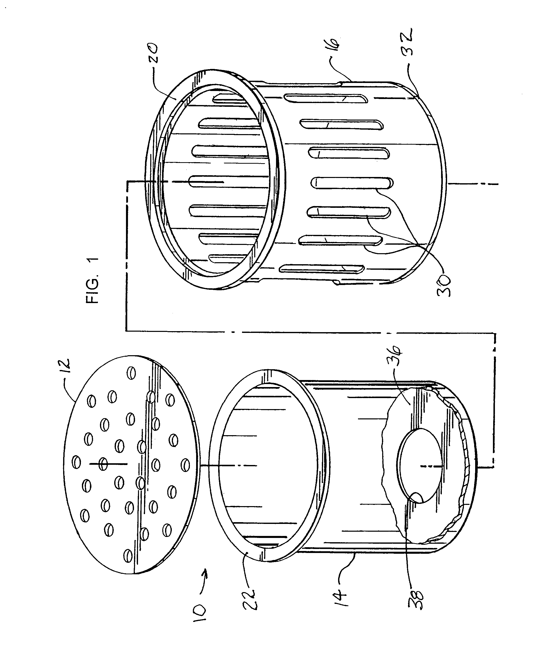
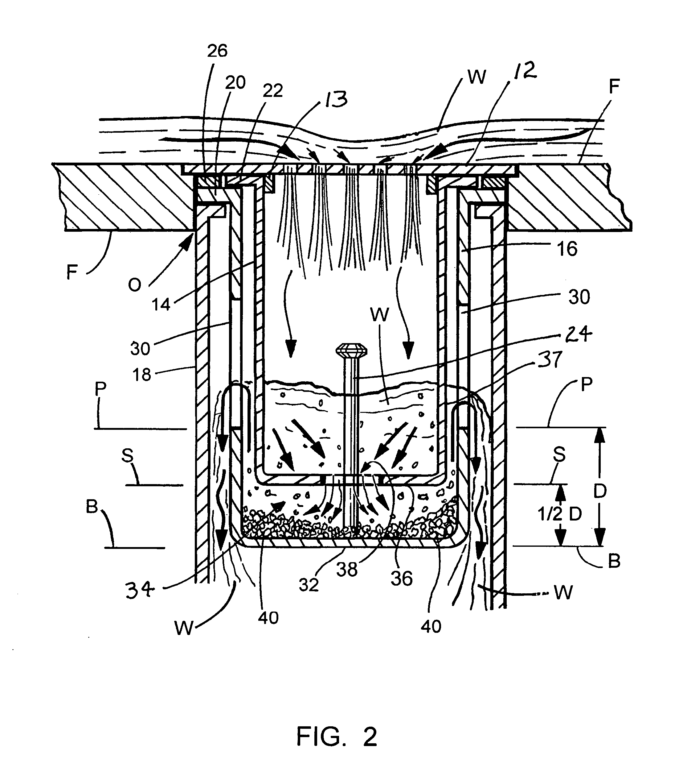
[0024]As shown in FIGS. 1 and 2, the present invention is a clog free drain 10 including a drain plate 12, a sleeve 14, and a basket 16. Drain plate 12 is a common element of floor mounted drain systems such as a stall shower and certain tubs. As illustrated in FIG. 2, the drain plate 12 is disposed in the floor or other support plane F, generally over the drain pipe 18 which carries the waste water off to the sewer system (not shown). Basket 16 conventionally includes such as an annular flange 20 to support the basket 16, such as on the upper reach of the drain pipe 18, at a...


PUM


Abstract

A clog free drain for a surface water drain such as that utilized in a tub or stall shower including a basket having side openings permitting waste water to flow there through and into the drain pipe in which the basket is disposed. Directing waste water into the basket is by a sleeve located coaxially of the basket and the drain pipe and below the drain plate whereby the waste water flows through the sleeve, out an opening in the bottom thereof in to the closed bottom of the basket. The waste water accumulates below and into the sleeve and into the basket to a level of the side openings in the basket where it flows into the drain pipe. Pooling of the waste water in the bottom of the basket allows the debris, hair, soap scum and other suspended particles to accumulate in the bottom of the basket and thus separated from the waste water flowing in to the drain pipe.

Description

CROSS REFERENCE TO RELATED APPLICATIONS[0001]This application claims benefit of prior U.S. Provisional Application Ser No. 60 / 661,780, filed Mar. 15, 2005, the content of which is fully incorporated herein by reference.STATEMENT REGARDING FEDERALLY SPONSORED RESEARCH OR DEVELOPMENT[0002]Not applicableREFERENCE TO A MICROFICHE APPENDIX[0003]Not applicableFIELD OF THE INVENTION[0004]The present invention relates to surface drains for plumbing, such as for floor drains, kitchen and bathroom sinks, bath tubs, and showers. Due to the flexible sizing and unique features, it may also be utilized as a large capacity drainage for floors, large sinks and special purpose drains. In particular, the invention relates to apparatus for straining out particulate material sloughed into waste water such as hair while bathing, or grease and small food particles such as coffee grinds in the kitchen sink, while collecting the particulate matter and keeping it from later clogging the drain. This inventio...

Claims


Application Information

Patent Timeline
IPC IPC(8): E03C1/26
CPCE03C1/282
Inventor KAMBEYANDA, DONA M.
Owner KAMBEYANDA DONA M
Why Eureka
Try Eureka