
Radar sensor for motor vehicles

a technology for a radar sensor and a motor vehicle, applied in the direction of antenna adaptation in movable bodies, instruments, antennas, etc., can solve the problems of inability to accurately determine, distorted speed measurement by wheel slip, and relatively weak echo, so as to simplify the targeted evaluation of this signal, improve the accuracy and reliability of the automatic blindness recognition system

Inactive Publication Date: 2006-12-19
ROBERT BOSCH GMBH
View PDF26 Cites 25 Cited by
  • Summary
  • Abstract
  • Description
  • Claims
  • Application Information

AI Technical Summary

Benefits of technology

The present invention provides a way to increase the usefulness of a radar sensor in vehicles by directing one of its lobes at the roadway surface. This allows for better measurement of the ground speed of the vehicle and the distance at which the radar lobe impinges on the roadway surface. By measuring these parameters, the sensor can better control the vehicle's speed and prevent accidents. Additionally, the radar sensor can also be used to check the alignment of the sensor and detect blinding of the sensor. Overall, this invention improves the accuracy and reliability of radar sensors in vehicles and ensures safe driving.

Problems solved by technology

For conventional radar sensors as well, a weak echo from the roadway surface is always received as “background”; this echo is relatively weak, however, since the slightly divergent radar beam has not expanded enough to impinge on the roadway surface until it is a relatively large distance from the sensor.
For converting the wheel speed into the vehicle speed, however, the effective wheel diameter must be known, and it is not possible to accurately determine the latter because of fluctuations in the tire pressure, load, etc.
In addition, the speed measurement may be distorted by wheel slip.
For this reason, the speed measurements using wheel speed sensors fail primarily in driving situations in which individual, or all, wheels of the vehicle experience significant slip or lock-up.
Otherwise, there is a risk that the radar lobes either pass over vehicles at a distance when the alignment is too high, or strike the ground before reaching the vehicle at a distance when the alignment is too low.
Although the radar waves are able to penetrate rain and fog better than the human eye, the radar sensor may be blinded due to various causes.
Possible reasons for such blinding, besides the sensor misalignment already mentioned, are errors or breakdowns of the sensor electronics, and in particular, deposits of snow, slush, or ice on the radar antenna or on the lens which bundles the radar beams.
One disadvantage of this system, however, is that blinding of the sensor is erroneously identified in a very low-reflecting environment, such as when driving on a seldom traveled road in barren areas, where there are also no reflecting targets on the roadside.

Method used


Image

  • Radar sensor for motor vehicles
  • Radar sensor for motor vehicles
  • Radar sensor for motor vehicles

Examples


Embodiment Construction

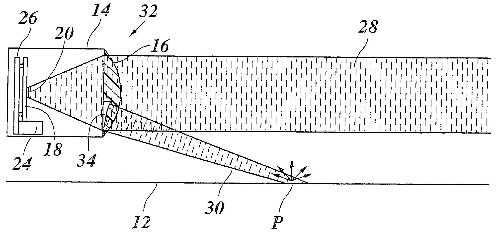
[0026]Radar sensor 10 shown in FIG. 1 is installed on the front side of a motor vehicle, not shown, at a specified distance above roadway surface 12, and has a housing 14 which is closed off on the front side by a lens 16 (condenser element) made of a plastic that is transparent to radar waves. Multiple patches 20, 22, which are used as radar sources and fed by a microwave oscillator 24 via microwave conductors are mounted inside housing 14, on a substrate 18 approximately in the focal plane of lens 16.

[0027]In the example shown, patches 20, 22 are simultaneously used as receiving antennae for the radar echo. The received signals are evaluated by an electronic evaluation system mounted on a plate 26 behind substrate 18.

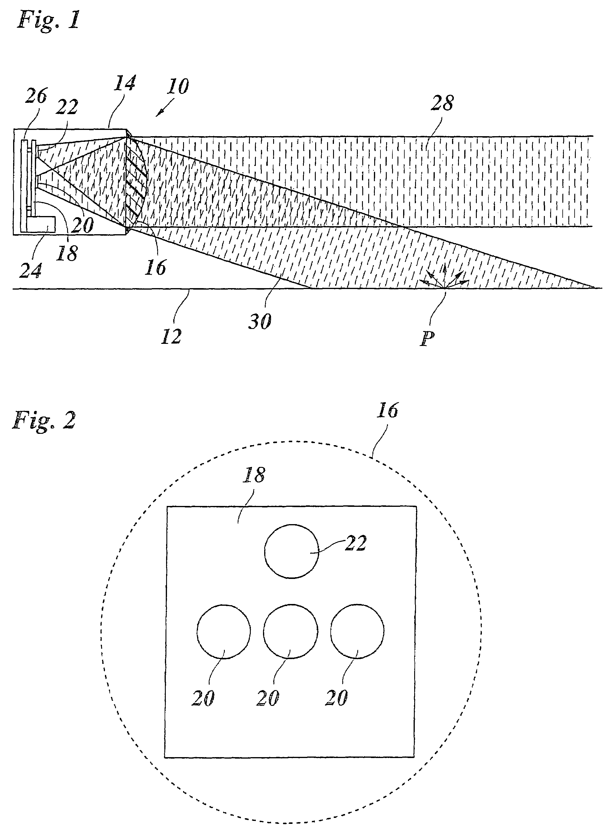
[0028]The system of patches 20, 22 on substrate 18 is illustrated in FIG. 2. The outline of lens 16 is represented by a dashed line. Three patches 20 are situated next to one another on a line which runs horizontally, and thus parallel to roadway surface 12. The middl...


PUM


Abstract

Radar sensor for motor vehicles, having a transmitter and receiver unit whose directional characteristic has multiple lobes, at least one of which is directed parallel to the roadway surface, at least one other lobe being directed obliquely to the roadway surface.

Description

FIELD OF THE INVENTION[0001]The present invention relates to a radar sensor for motor vehicles, having a transmitter and receiver unit whose directional characteristic has multiple lobes, at least one of which is directed parallel to the roadway surface. The present invention further relates to various uses of such a radar sensor.BACKGROUND INFORMATION[0002]Radar sensors are used in motor vehicles, for example in an Adaptive Cruise Control (ACC) system, and are used within such a system to measure the distance from a vehicle traveling ahead, so that the speed of the subject vehicle can be adapted to that of the vehicle traveling ahead. A description of such an ACC system can be found, for example, in Winner: “Adaptive Cruise Control” in Automotive Electronics Handbook, Ronald K. Jurgen (editor), 2nd Edition, McGraw-Hill (1999), Chapter 30.1. The principle of distance measurement is based on a measurement of the transit time of the radar echo. The Doppler effect also allows a direct ...

Claims


Application Information

Patent Timeline
Patent Type & Authority Patents(United States)
IPC IPC(8): G01S13/93G01S7/02G01S7/03G01S7/40G01S13/60G01S13/92G01S13/931H01Q1/32H01Q15/02H01Q19/06
CPCG01S7/4026G01S13/60G01S13/931H01Q1/3233H01Q15/02H01Q19/062G01S7/4056G01S2007/4039G01S2007/4082G01S2007/4091G01S2007/4034G01S2013/9353G01S2013/9375G01S2013/9321G01S2013/93271G01S2013/932G01S7/4039G01S7/4034G01S7/4091G01S7/4082
Inventor BEEZ, THOMASLEHRE, KLAUS
Owner ROBERT BOSCH GMBH
Learn More