System and method for providing quality of service transport at an air interface of a telecommunications network

a technology of air interface and quality of service, applied in the field of wireless telecommunications technology, can solve the problems of lack of knowledge, inability to provide wireless infrastructure, and inability to carry out user applications in wireless traffic, and achieve the effect of ease of internet protocol transpor

Active Publication Date: 2006-12-19
CISCO TECH INC
View PDF21 Cites 16 Cited by
  • Summary
  • Abstract
  • Description
  • Claims
  • Application Information

AI Technical Summary

Benefits of technology

[0005]The present invention provides various technical advantages over conventional quality of service approaches. For example, one technical advantage is to provide a class of service indication at a base transceiver station in an air interface of a telecommunications network. Another technical advantage is to implement an all Internet Protocol distributed system with loose coupling between the Internet Protocol and the radio layers. Yet another technical advantage is to provide ease of Internet Protocol transport in a radio access network. Other examples may be readily ascertainable by those skilled in the art from the following figures, description, and claims.

Problems solved by technology

However, network architectures do not provide a wireless infrastructure that can support the Internet Protocol in a seamless manner.
Though the radio access network infrastructure can support the Internet Protocol as a transport medium, there is no knowledge concerning user applications being carried in the wireless traffic without this termination at the base transceiver station.
Such lack of knowledge is detrimental to the quality of service for the user traffic and hampers the ability to provision a transport path through the network.
This approach is not very scalable and may break the quality of service associated with the supported applications.

Method used


Image

  • System and method for providing quality of service transport at an air interface of a telecommunications network
  • System and method for providing quality of service transport at an air interface of a telecommunications network

Examples


Embodiment Construction

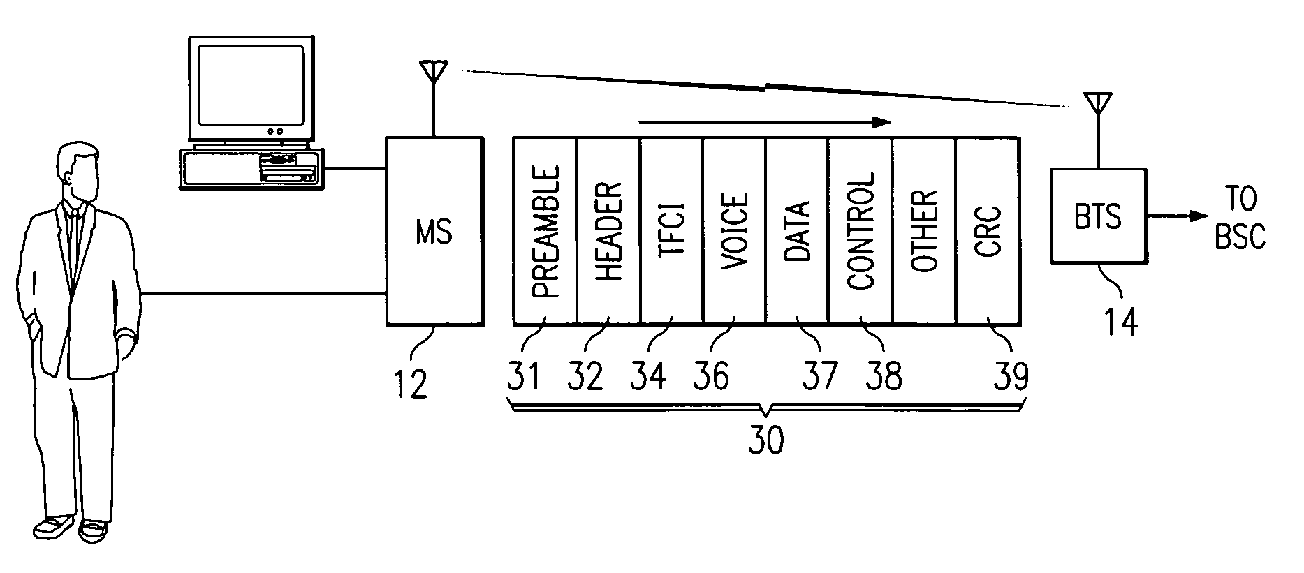
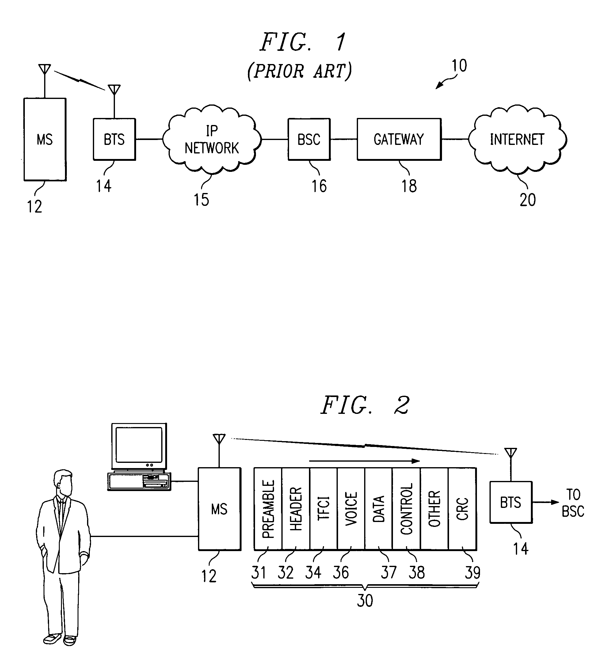
[0009]FIG. 1 is a block diagram of an exemplary telecommunications network 10. Telecommunications network 10 includes a mobile station 12, a base transceiver station 14, an Internet Protocol (IP) network 15, a base station controller 16, a gateway node 18, and an Internet network 20. Telecommunications network 10 may also include other conventional components as desired.

[0010]In operation, mobile station 12 initiates a communication session with base transceiver station 14. Base transceiver station 14 establishes the communications session with mobile station 12. Mobile station 12 provides wireless telecommunications traffic, which may include voice, data, and / or control information, to base transceiver station 14. Base transceiver station 14 receives the wireless telecommunications traffic and processes the information request for appropriate forwarding to base station controller 16 over IP network 15. Base station controller 16 processes the information request and forwards it on ...


PUM


Abstract

A telecommunications network includes a mobile station that generates wireless telecommunications traffic in radio frames for transmission to a base transceiver station. The mobile station sets a TFCI field in the radio frame to provide a class of service indication for the payload information carried in the radio frame. The TFCI field is set according to a priority of the payload information to be carried in the radio frame. The base transceiver station receives the wireless telecommunications traffic and identifies the class of service indications carried in the radio frame. The base transceiver station encapsulates the radio frame into Internet Protocol packets. The base transceiver station maps the transport format combination indicator field into a differentiated services code point field in header information of the Internet Protocol packets. The base transceiver station forwards the Internet Protocol packets to a base station controller over an Internet Protocol network according to the identified class of service indication in the differentiated services code point field.

Description

TECHNICAL FIELD OF THE INVENTION[0001]The present invention relates in general to wireless telecommunications technology and more particularly to a system and method for providing quality of service transport at an air interface of a telecommunications network.BACKGROUND OF THE INVENTION[0002]Wireless and cellular networks are evolving into a model that implements the Internet Protocol. However, network architectures do not provide a wireless infrastructure that can support the Internet Protocol in a seamless manner. Wireless traffic originating from a mobile station is not terminated by a receiving base transceiver station. Though the radio access network infrastructure can support the Internet Protocol as a transport medium, there is no knowledge concerning user applications being carried in the wireless traffic without this termination at the base transceiver station. Such lack of knowledge is detrimental to the quality of service for the user traffic and hampers the ability to p...

Claims


Application Information

Patent Timeline
Patent Type & Authority Patents(United States)
IPC IPC(8): H04L12/28H04L12/56H04L12/66H04L29/06H04L29/08H04B7/212H04B7/216H04W28/18H04W28/24
CPCH04W28/24H04L69/161H04L69/165H04W28/18H04L69/16H04W28/06H04W40/00
Inventor IYER, JAYARAMAN RAMASWAMYSMITH, MALCOLM M.
Owner CISCO TECH INC
Why Eureka
Try Eureka