
Circuit arrangement for the analogue suppression of echoes

a circuit arrangement and analog suppression technology, applied in the field of circuit arrangement, can solve the problems of large technological circuit complexity, inability of digital linear echo compensator inability to compensate non-linear distortion of transmitted signals, so as to achieve low noise, influence linearity and noise, and high linear

Inactive Publication Date: 2006-12-19
LANTIQ BET GMBH & CO KG
View PDF7 Cites 1 Cited by
  • Summary
  • Abstract
  • Description
  • Claims
  • Application Information

AI Technical Summary

Benefits of technology

"The present invention proposes a circuit arrangement for suppressing analogue echoes in a cost-effective and efficient manner. The circuit arrangement includes first circuit means for emulating the behavior of the transmission line, second circuit means for emulating the behavior of the transformer, and third circuit means for correcting the signal from the transformer. The circuit arrangement can be adapted to the particular transmission line used in each case, and it uses passive elements to emulate the echo signal. The invention is particularly useful in communication devices for ISDN and XDSL transmission systems. It reduces the complexity of the circuit arrangement and power consumption, and it improves echo cancelling and reduces demands on the analog / digital converter."

Problems solved by technology

This digital linear echo compensator is not able to compensate non-linear distortions of the transmitted signal path, which are found in the echo.
The main technical problem, which arises in the case of hybrid-circuits, is the precise emulation of the transmitted signal related to that point in the transmission system, at which the emulated transmitted signal should be subtracted from the overall signal.
The term “bridge tap” describes stub cables connected to the line wires of the transmission line, which are provided for the connection of further subscribers, but which are not terminated with a suitable intrinsic impedance and can cause reflections as a result.
The problem, therefore, arises of emulating as accurately as possible the impedance of the transmission line and transformer in all cases of application.
Further, the power loss of the hybrid-circuit should be as low as possible.
In the case of the first solution described above, considerable technological circuit complexity is necessary, since the overall transmitted signal path must be implemented twice.
Any mismatch between the two transmitted signal paths results in inadequate echo suppression.
Considerable power consumption is required to keep noise within tolerable limits.
Very high power consumption is also required in this case to keep noise within tolerable limits.

Method used


Image

  • Circuit arrangement for the analogue suppression of echoes
  • Circuit arrangement for the analogue suppression of echoes
  • Circuit arrangement for the analogue suppression of echoes

Examples


Embodiment Construction

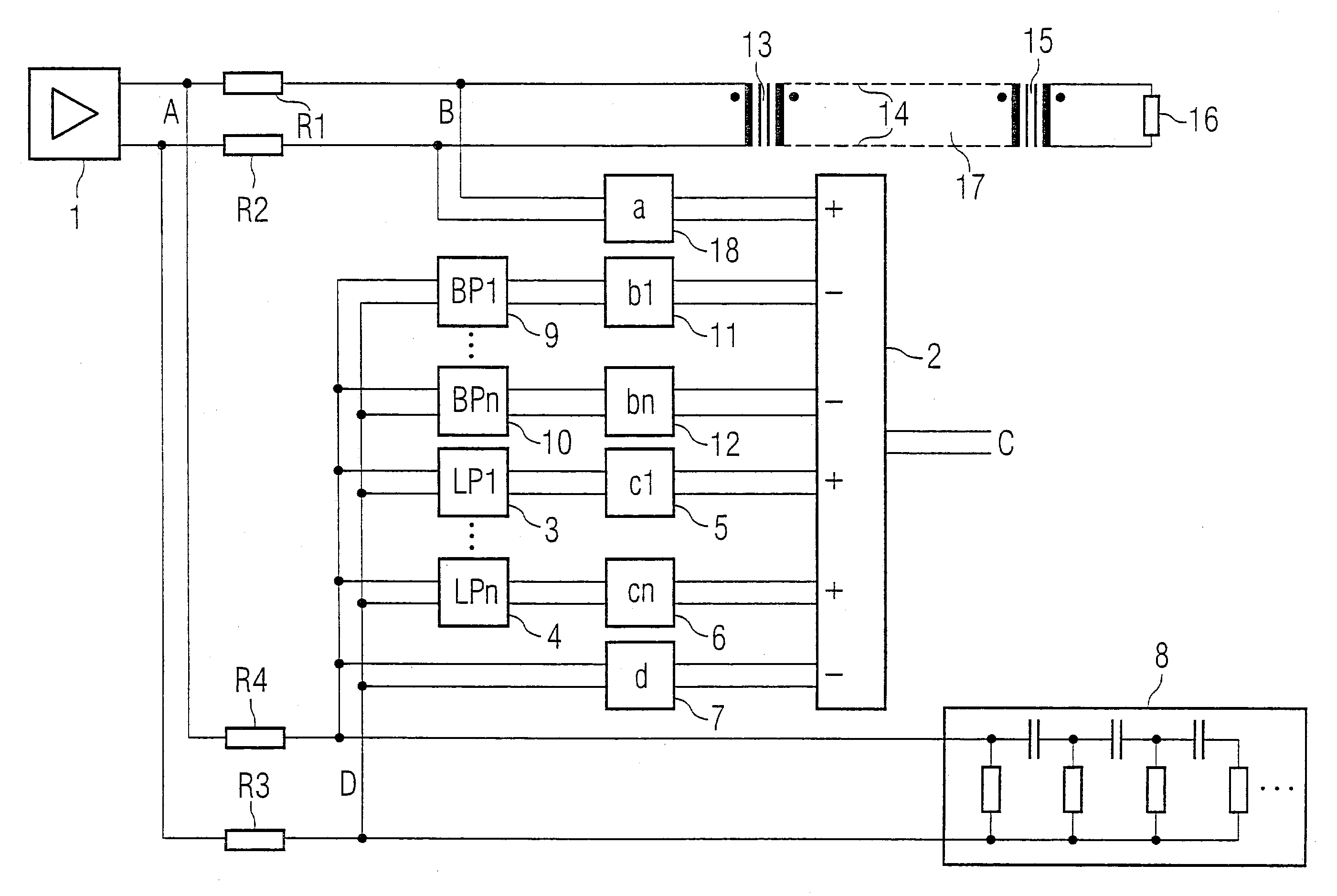
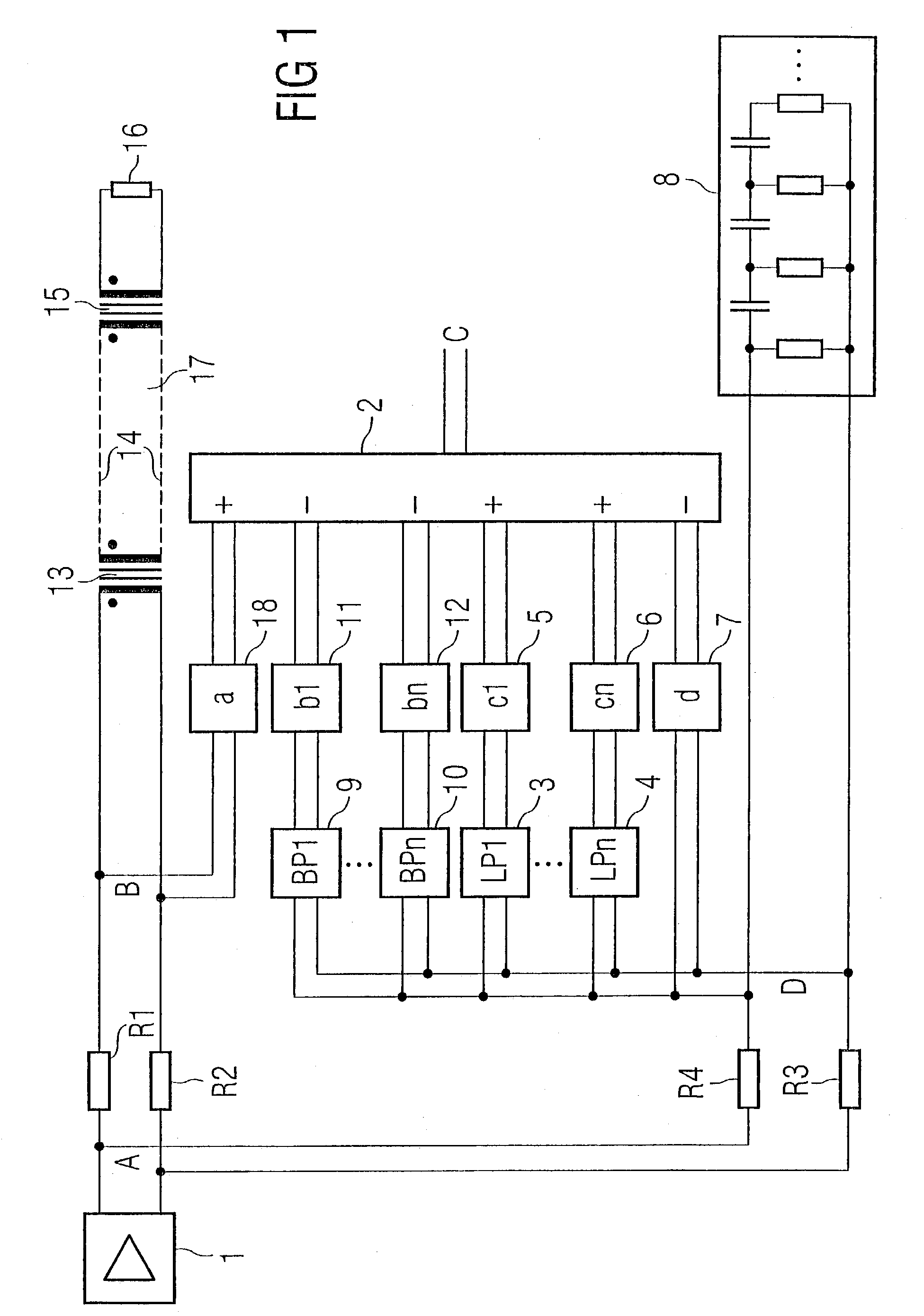
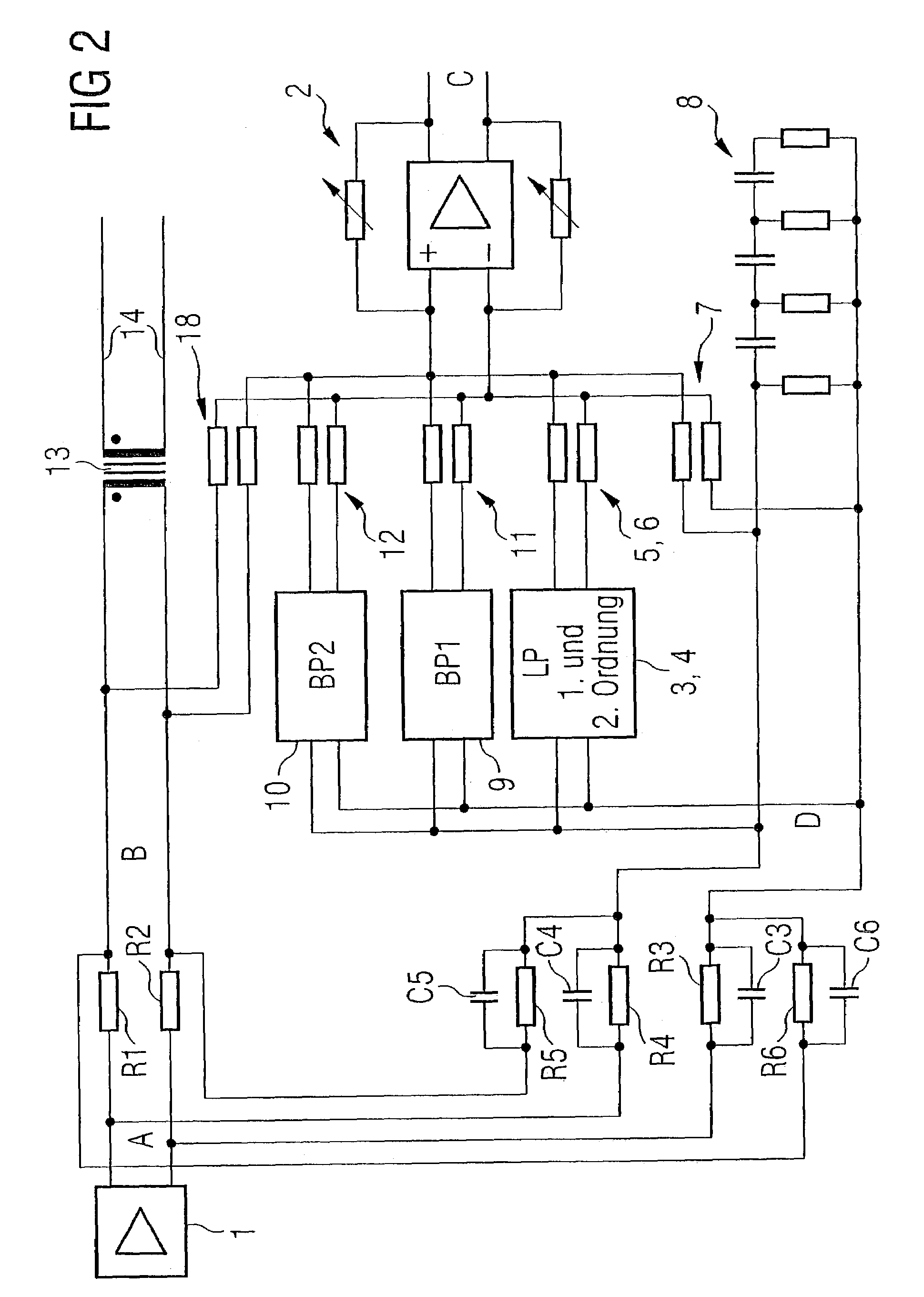
[0025]FIG. 1 shows a hybrid circuit of a communication device connected to a transmission line 17, for example, an SDSL transmission line. As normal in itself, the communication device has a line driver 1, which is connected via protective resistors R1 and R2 to a transformer 13. The transformer 13 represents the beginning of the transmission line 17. Stub cables or bridge taps 14 are connected to the transmission line 17. On the receiver end, a transformer 15 is equally provided, which is connected on the input side to the transmission line 17 and is terminated on the output side by a terminal resistor 16.

[0026]As clear from FIG. 1, the output voltage of the line driver 1 corresponding to the pure transmitted signal lies on circuit point A shown in FIG. 1, whereas the sum of the received signal obtained over the transmission line 17 and the transmitted signal to be transmitted over the transmission line 17 lies on line point B equally shown in FIG. 1. In order to obtain the pure re...


PUM


Abstract

A circuit arrangement for the analogue suppression of echoes, as in particular can be used in a hybrid-circuit for DSL-transmission systems, comprises a replica (8) for emulating the behaviour of the transmission line (17). In addition, a circuit (3, 4) for emulating the behaviour of the transmitter (13) is provided, which comprises at least one lowpass (3, 4). Furthermore, a replica (9, 10) for emulating the behaviour of bridge taps (14) can also be provided, which comprises at least one bandpass (9, 10). Additionally, a replica (19) for emulating the behaviour of the line driver (1) can also be provided.

Description

BACKGROUND OF THE INVENTION[0001]The present invention relates to a circuit arrangement, which is provided for the analogue suppression of echoes as regards the received signal of a communication device connected via a transformer to a transmission line.[0002]In the case of ISDN and DSL transmission systems, data is transmitted between the exchange and the subscriber via a twisted line wire pair, whereby each of the two line wires is provided simultaneously for both transmission directions, that is to say, for the transmission direction from the exchange to the subscriber and for the transmission direction from the subscriber to the exchange. The signal lying on the line wires is, therefore, composed of a received signal portion and a transmitted signal portion. In order to obtain the received signal—also described as “far end signal”—on the subscriber end, the transmitted or echo signal—also described as “near end echo”—must be subtracted from the overall signal. On the one hand, t...

Claims


Application Information

Patent Timeline
Patent Type & Authority Patents(United States)
IPC IPC(8): H04M9/08H03H7/12H04B3/20H04B3/23H04M1/58
CPCH04B3/23
Inventor BLON, THOMASEICHLER, THOMASGROPL, MARTINLAASER, PETER
Owner LANTIQ BET GMBH & CO KG
Learn More