Check patentability & draft patents in minutes with Patsnap Eureka AI!
Acceleration detector
What is Al technical title?
Al technical title is built by PatSnap Al team. It summarizes the technical point description of the patent document.
a detector and acceleration technology, applied in the direction of acceleration measurement using interia forces, force/torque/work measurement apparatus, instruments, etc., can solve the problems of high manufacturing cost, high apparatus such as an ion implanter, and high cos
Inactive Publication Date: 2006-12-26
OKADA KAZUHIRO
View PDF115 Cites 27 Cited by
Summary
Abstract
Description
Claims
Application Information
AI Technical Summary
This helps you quickly interpret patents by identifying the three key elements:
Problems solved by technology
Method used
Benefits of technology
Benefits of technology
[0008]A first object of this invention is to provide a novel detector which can detect a physical quantity such as force, acceleration or magnetism, etc. without carrying out temperature compensation, and can be supplied at a low cost.
Problems solved by technology
In addition, in order to manufacture the above described detectors, a high level process for processing the semiconductor substrate is required, and a high cost apparatus such as an ion implanter is also required.
For this reason, there is the problem that the manufacturing cost becomes high.
Method used
Image
Click on the blue label to locate the original text in one second.
Reading with bidirectional positioning of images and text.
Examples
embodiment
§5. Embodiment Having Test Function
[0157]Generally, in the case of mass producing any detectors to deliver them to the market, the test process is conducted prior to shipping. That is, the work for confirming whether or not the detector normarily carries out the detecting operation is conducted. Also in the previously described acceleration detector, it is preferable to carry out a test prior to shipping. In order to test the acceleration detector, an approach is generally employed to actually apply an acceleration thereto and confirm an electric signal outputted at this time. However, an equipment for producing an acceleration is required for such a test. As a result, the test system becomes large.
[0158]In the embodiment described below, test prior to shipping can be carried out without using such a large test system. FIG. 19 is a side cross sectional view showing the structure of an acceleration detector according to the embodiment having such a test function. This detector compri...
PUM
Property
Measurement
Unit
temperature
aaaaa
aaaaa
acceleration
aaaaa
aaaaa
capacitance
aaaaa
aaaaa
Abstract
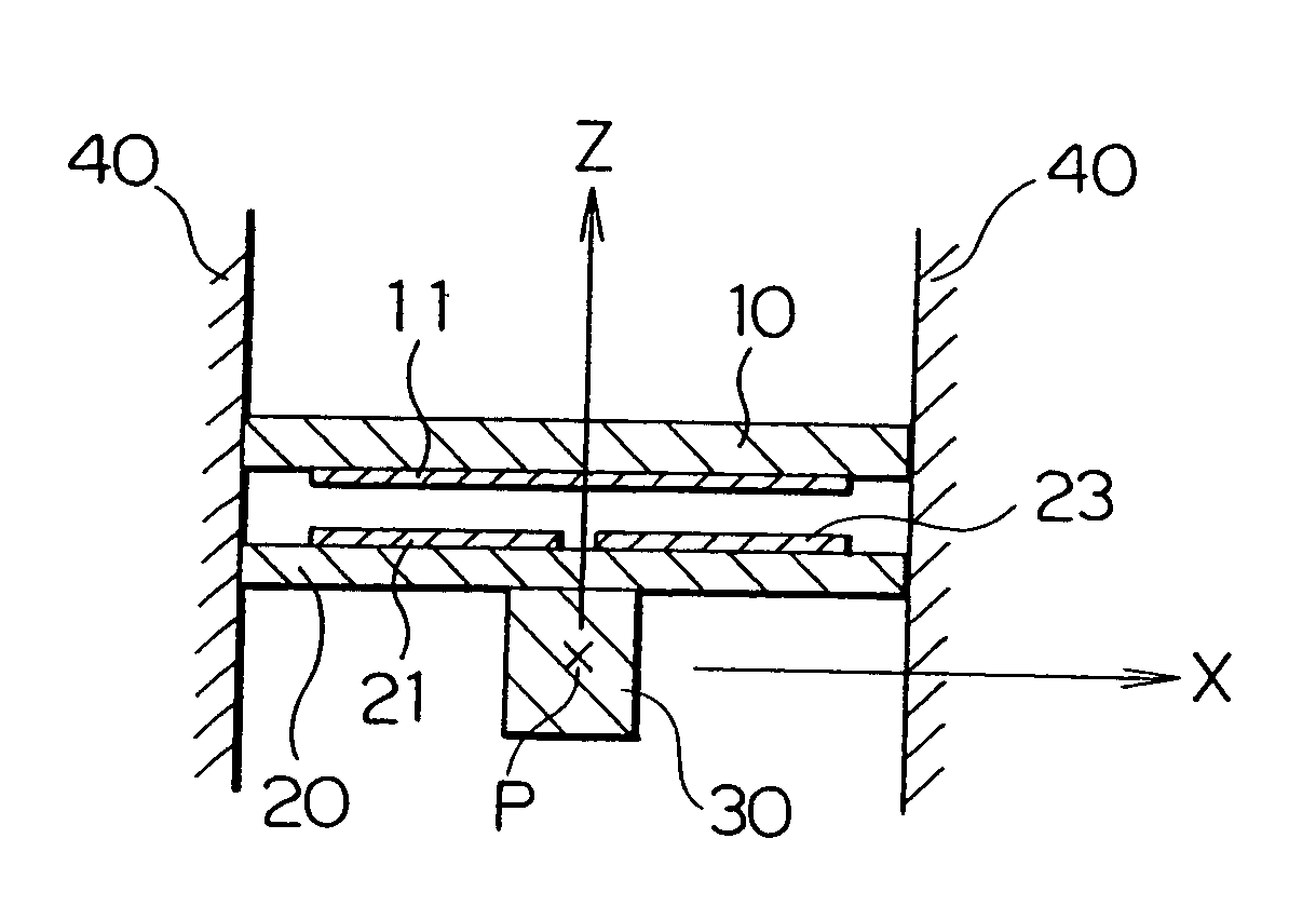
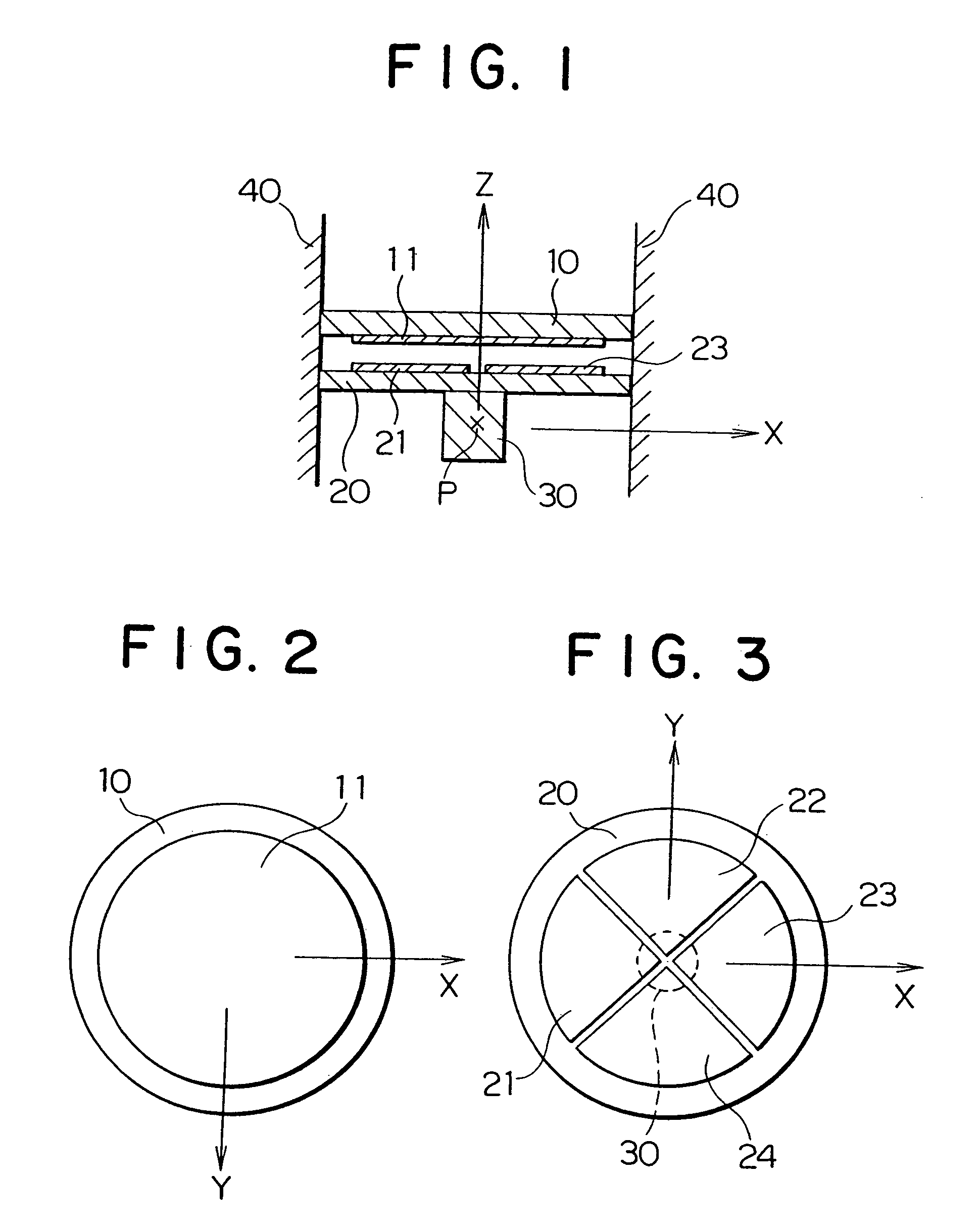
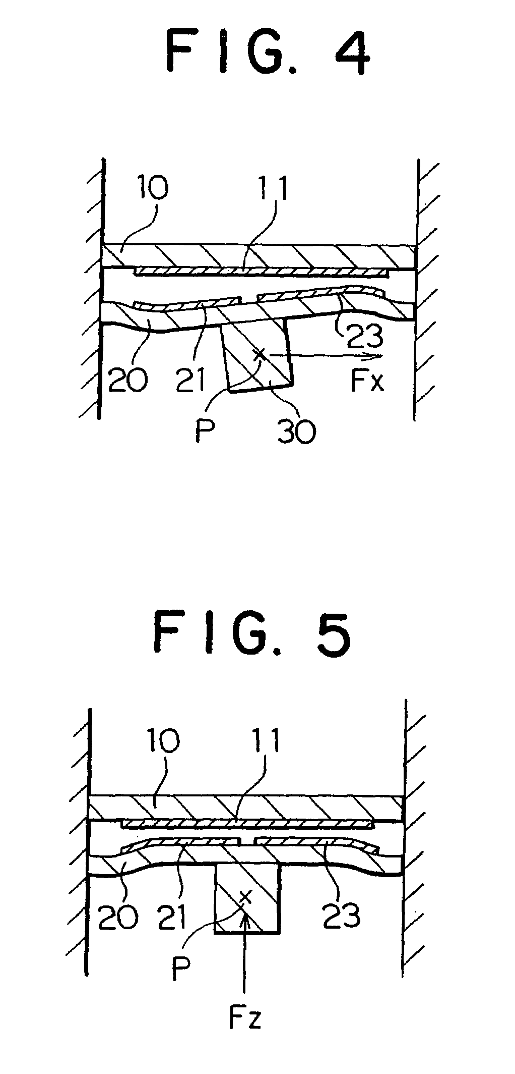
An electrode layer is formed on the upper surface of a first substrate, and a processing for partially removing the substrate is carried out in order to allow the substrate to have flexibility. To the lower surface of the first substrate, a second substrate is connected. Then, by cutting the second substrate, a working body and a pedestal are formed. On the other hand, a groove is formed on a third substrate. An electrode layer is formed on the bottom surface of the groove. The third substrate is connected to the first substrate so that both the electrodes face to each other with a predetermined spacing therebetween. Finally, the first, second and third substrates are cut off every respective unit regions to form independent sensors, respectively. When an acceleration is exerted on the working body, the first substrate bends. As a result, the distance between both the electrodes changes. Thus, an acceleration exerted is detected by changes in an electrostatic capacitance between both the electrodes.
Description
[0001]This application is divisional of application Ser. No. 10 / 247,772 filed on Sept. 19, 2002, now U.S. Pat No. 6,779,408, which is a divisional of application Ser. No. 09 / 907,444 filed on Jul. 17, 2001 (now U.S. Pat. No. 6,477,903) which is a divisional of application Ser. No. 09 / 614,850 filed on Jul. 12, 2000 (now U.S. Pat. No. 6,314,823), which is a divisional of application Ser. No. 09 / 375,334 filed on Aug. 16, 1999 (now U.S. Pat. No. 6,158,291), which is a divisional of application Ser. No. 09 / 109,560 filed on Jul. 2, 1998 (now U.S. Pat. No. 6,053,057) which is a divisional of application Ser. No. 08 / 819,357 filed on Mar. 18, 1997 (now U.S. Pat. No. 5,811,693) which is a divisional of application Ser. No. 08 / 647,178 filed May 9, 1996 (now U.S. Pat. No. 5,639,973) which is a divisional of application Ser. No. 08 / 394,310 filed on Feb. 24, 1995 (now U.S. Pat. No 5,531,002) which is a divisional of application Ser. No. 08 / 292,496 filed on Aug. 18, 1994 (now U.S. Pat. No. 5,406,84...
Claims
Application Information
Patent Timeline
Application Date:The date an application was filed.
Publication Date:The date a patent or application was officially published.
First Publication Date:The earliest publication date of a patent with the same application number.
Issue Date:Publication date of the patent grant document.
PCT Entry Date:The Entry date of PCT National Phase.
Estimated Expiry Date:The statutory expiry date of a patent right according to the Patent Law, and it is the longest term of protection that the patent right can achieve without the termination of the patent right due to other reasons(Term extension factor has been taken into account ).
Invalid Date:Actual expiry date is based on effective date or publication date of legal transaction data of invalid patent.
