Control apparatus for internal combustion engine

a control apparatus and internal combustion engine technology, applied in mechanical apparatus, electric control, machines/engines, etc., can solve the problems of power degradation, increased emission of harmful gas components, and apt function degradation of the second fuel injection valve, so as to achieve high accuracy and without degrading the performance of the internal combustion engine

Active Publication Date: 2006-12-26
TOYOTA JIDOSHA KK
View PDF20 Cites 17 Cited by
  • Summary
  • Abstract
  • Description
  • Claims
  • Application Information

AI Technical Summary

Benefits of technology

[0013]In view of the foregoing, an object of the present invention is to provide, for an internal combustion engine including a first fuel injection mechanism for injecting fuel into a cylinder and a second fuel injection mechanism for injecting fuel into an intake manifold, both partaking in fuel injection, a control apparatus that can have knocking sensed at high accuracy by a knock sensor, preventing the knock sensor from sensing vibration in connection with an operation of the first fuel injection mechanism without degrading the performance of the internal combustion engine.

Problems solved by technology

Therefore, the second fuel injection valve is apt to exhibit function degradation and occurrence of an abnormal event due to carbon clogging and the like, as compared to the fuel injection valve conventionally and widely employed in manifold injection type internal combustion engines.
Degradation in the performance and occurrence of an abnormal event at the fuel injection valve will prohibit proper operation of the internal combustion engine, resulting in the possibility of posing problems such as power degradation and increase in the emission of harmful gas components.
Thus, it is difficult to sense knocking at high accuracy by a knock sensor when vibration in connection with the operation of the in-cylinder injector overlaps with the knock determination period in an engine with an in-cylinder injector.
If the injection period of the in-cylinder injector is shortened, the required fuel injection quantity may not be satisfied.
There is a possibility of having difficulty in ensuring the engine performance.

Method used


Image

  • Control apparatus for internal combustion engine
  • Control apparatus for internal combustion engine
  • Control apparatus for internal combustion engine

Examples


first embodiment

[0041

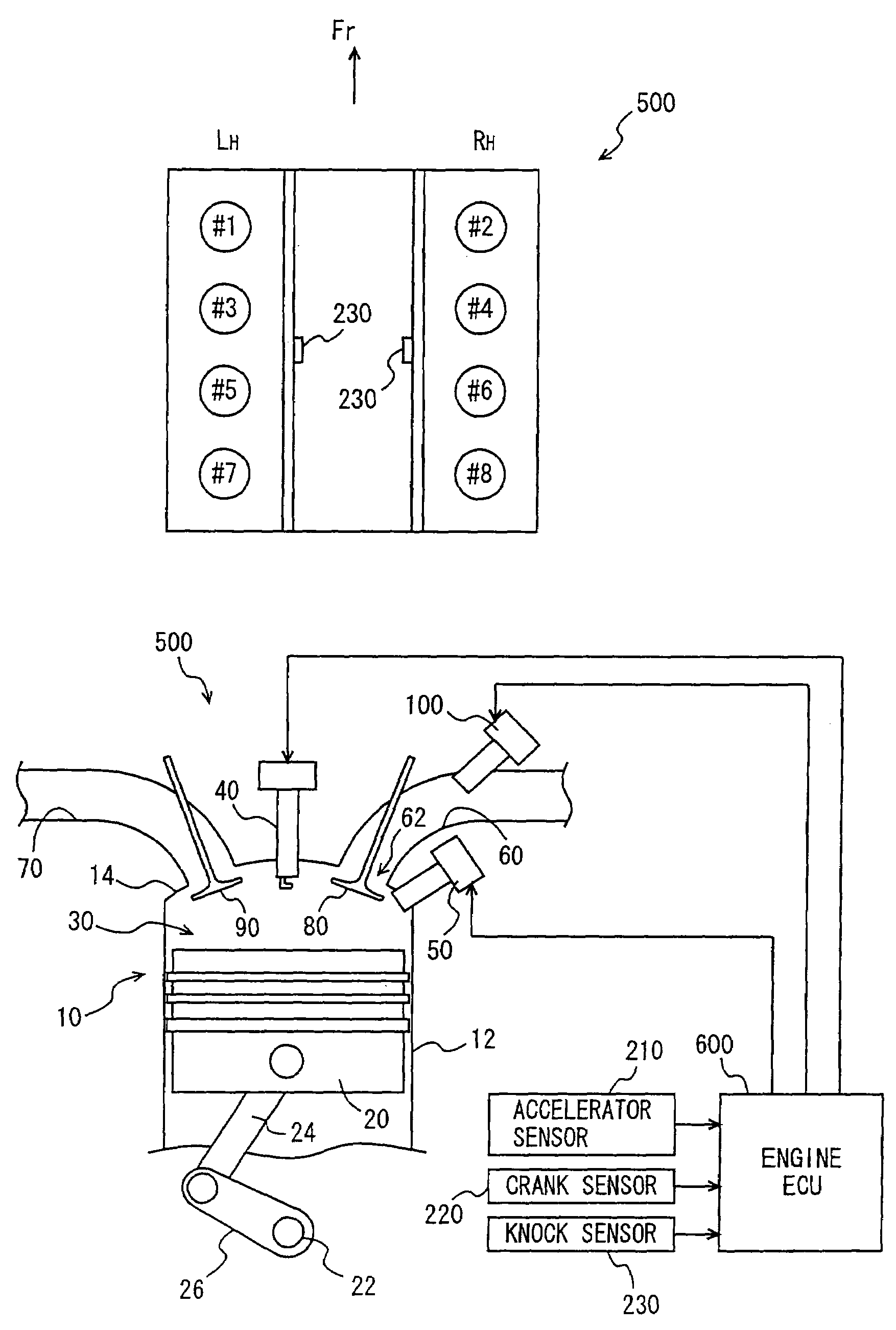
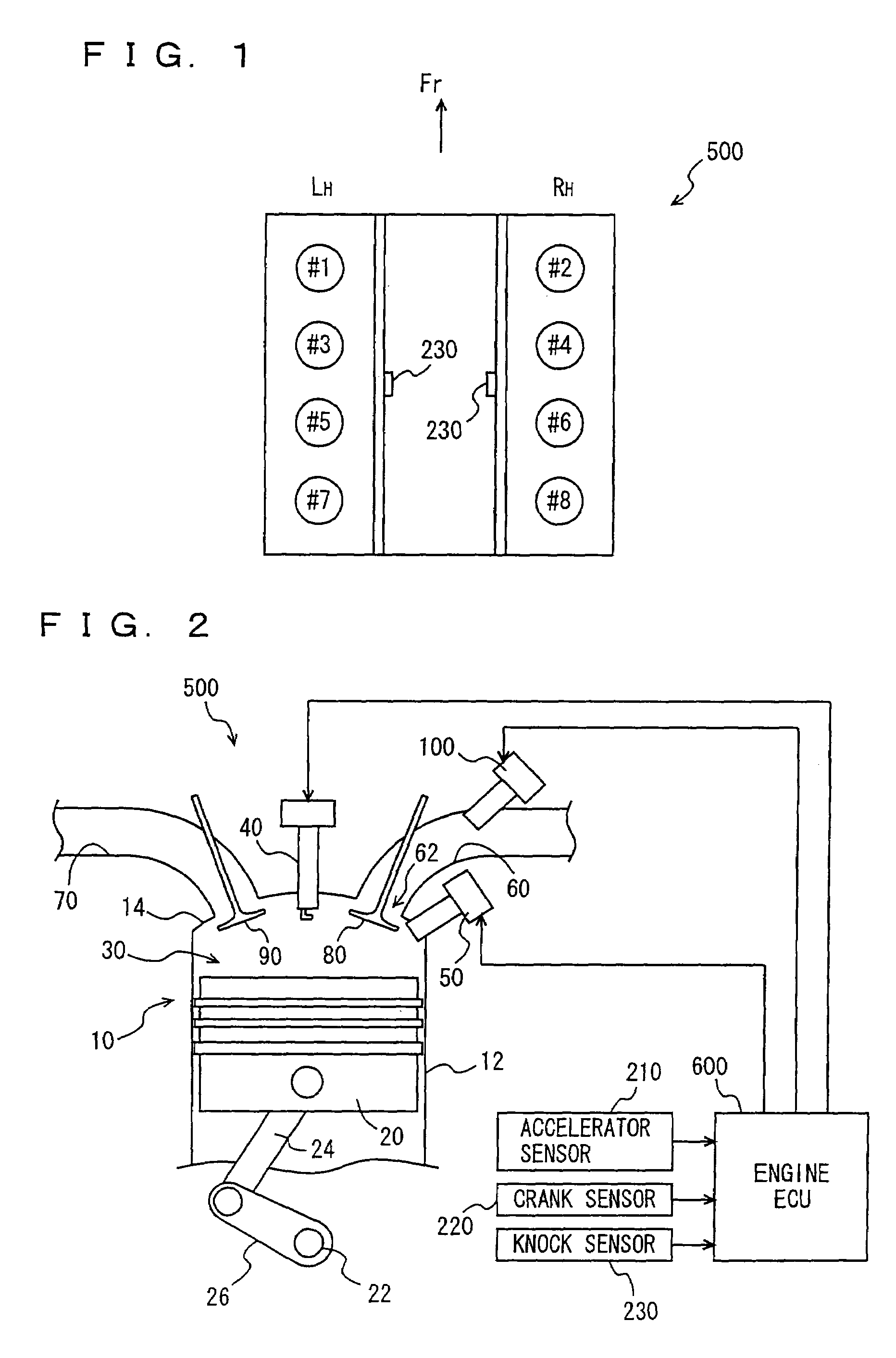
[0042]An engine system including an engine ECU (Electronic Control Unit) identified as a control apparatus for an internal combustion engine according to a first embodiment of the present invention will be described hereinafter. FIG. 1 represents the cylinder arrangement of an engine 500 under control of the engine ECU identified as the control apparatus of the present embodiment. As shown in FIG. 1, it is assumed that engine 500 is a reciprocating engine of 4 cycles, which is a V-8 gasoline engine including 8 cylinders. Although the present embodiment will be described based on such a V type 8-cylinder internal combustion engine, it is to be understood that the present invention is not limited thereto.

[0043]At the left bank in the V bank, cylinders #1, #3, #5 and #7 are arranged. At the right side bank, cylinders #2, #4, #6 and #8 are arranged. A knock sensor 230 is located between cylinder #3 and cylinder #5, and also between cylinder #4 and cylinder #6.

[0044]One of the 8 cyl...

second embodiment

[0070

[0071]A control apparatus for an internal combustion engine according to a second embodiment of the present invention will be described hereinafter. The engine system of the present embodiment is similar to the engine system of the first embodiment set forth above (FIGS. 1 and 2). Therefore, details of the description thereof will not be repeated here.

[0072]A control structure of a program executed by engine ECU 600 according to the second embodiment will be described with reference to FIG. 6. In the flow chart of FIG. 6, procedures identical to those in the process of the flow chart of FIG. 4 have the same step number denoted. Their specific contents are identical. Therefore, detailed descriptions thereof will not be repeated.

[0073]At S1000, engine ECU 600 shortens the injection period to TAUd. It is assumed that injection time Astart is not changed. At S1100, engine ECU 600 executes an engine quantity sufficiency determination process.

[0074]The injection quantity sufficiency ...

third embodiment

[0083

[0084]A control apparatus for an internal combustion engine according to a third embodiment of the present invention will be described hereinafter. The control apparatus for an internal combustion engine of the third embodiment has a hardware configuration similar to that of the first embodiment (FIGS. 1 and 2), likewise the second embodiment set forth above. The program executed by engine ECU 600 is similar to that of the second embodiment, except for the injection quantity sufficiency determination process (S1100 of FIG. 6). Therefore, detailed description thereof will not be repeated here.

[0085]A control structure of a program executed by engine ECU 600 of the third embodiment will be described with reference to FIG. 9. In the flow chart of FIG. 9, procedures identical to those in the process of the flow chart of FIG. 7 have the same step number denoted. Their specific contents are identical. Therefore, detailed descriptions thereof will not be repeated.

[0086]At S1200, engin...


PUM


Abstract

An engine ECU executes a program including the step of calculating an injection time Astart from the engine speed and load factor when arriving at the injection calculation timing of a cylinder located in the proximity of a knock sensor, the step of calculating an injection period TAU, the step of calculating an injection end time Aend, the step of shortening the injection time of an in-cylinder injector when the injection time Astart or injection end time Aend is within a KCS gate, and the step of calculating the port injection period so as to inject the insufficient injection quantity from an intake manifold injector when the required injection quantity will be insufficient as a result of shortening the injection period of the in-cylinder injector.

Description

[0001]This nonprovisional application is based on Japanese Patent Applications Nos. 2004-214623 and 2005-054103 filed with the Japan Patent Office on Jul. 22, 2004 and Feb. 28, 2005, respectively, the entire contents of which are hereby incorporated by reference.BACKGROUND OF THE INVENTION[0002]1. Field of the Invention[0003]The present invention relates to a control apparatus for an internal combustion engine including first fuel injection means (in-cylinder injector) for injecting fuel into a cylinder and second fuel injection means (intake manifold injector) for injecting fuel towards an intake manifold or intake port. Particularly, the present invention relates to an apparatus for controlling the internal combustion engine such that a knock sensor in a KCS (Knock Control System) does not erroneously sense vibration other than knocking.[0004]2. Description of the Background Art[0005]An internal combustion engine is well-known, including a first fuel injection valve (intake manifo...

Claims


Application Information

Patent Timeline
Patent Type & Authority Patents(United States)
IPC IPC(8): F02B3/00F02B7/00F02M43/00F02M51/00F02D35/02
CPCF02D35/027F02D41/3094F02D41/401F02P5/152F02D2250/14Y02T10/44F02D2041/281Y02T10/46Y02T10/40
Inventor MASHIKI, ZENICHIRONAKAMURA, NAOTO
Owner TOYOTA JIDOSHA KK
Why Eureka
Try Eureka