Termination circuit

a termination circuit and transistor technology, applied in the direction of logic circuit coupling/interface arrangement, digital transmission, pulse technique, etc., can solve the problems of inability to unify the voltage to be supplied to the gate terminal among transistors, the inability to unify the operation resistance value, and the inability to unify the connection with other circuits, so as to improve the matching characteristic of the termination circuit using the transistor as a termination resistor

Active Publication Date: 2006-12-26
FUJITSU LTD
View PDF6 Cites 20 Cited by
  • Summary
  • Abstract
  • Description
  • Claims
  • Application Information

AI Technical Summary

Benefits of technology

[0020]It is an object of the present invention to improve the matching characteristic of a termination circuit using a transistor as a termination resistor.
[0026]According to this configuration, since the resistance value of each resistance unit can be adjusted, the transmission line can be more appropriately matched.
[0029]According to this configuration, since a resistance device with a resistance characteristic better than the resistance unit is inserted, the change of the resistance characteristic of the resistance unit due to the signal level of the transmission line can be suppressed far more sufficiently.
[0031]According to this configuration, the resistance value of the resistance unit can be adjusted over a wider range or in finer steps, and accordingly, the transmission line can be more appropriately matched.
[0033]As described above, according to the present invention, the matching characteristic of a termination circuit using a transistor as a termination resistor can be improved.

Problems solved by technology

However, it is often difficult in connection with other circuits to unify a plurality of wiring layouts to the gate terminal of each transistor.
Therefore, in the technology disclosed in the Japanese Patent Application No. 2002-344300, voltage to be supplied to the gate terminal cannot be unified among transistors due to these different wiring layouts.
As a result, the on operation resistance values cannot be unified, and the transmission line cannot always be sufficiently matched.

Method used


Image

  • Termination circuit
  • Termination circuit
  • Termination circuit

Examples


Embodiment Construction

[0039]The preferred embodiments of the present invention are described below with reference to the drawings.

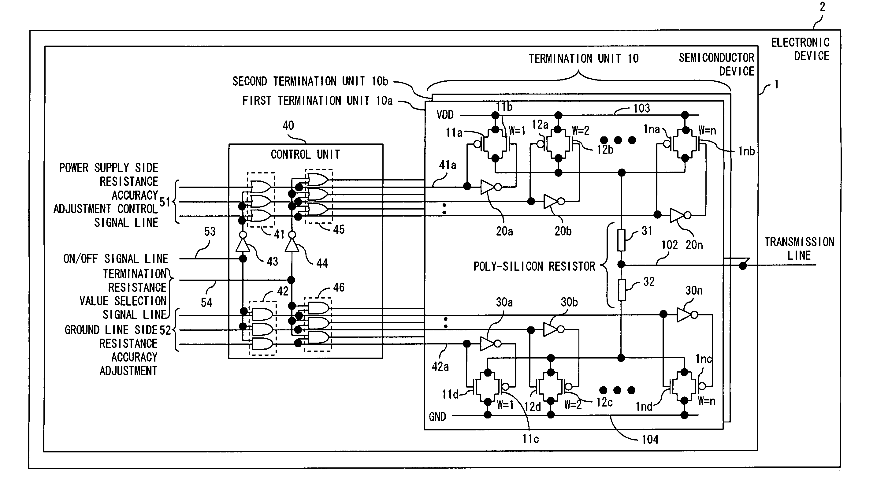
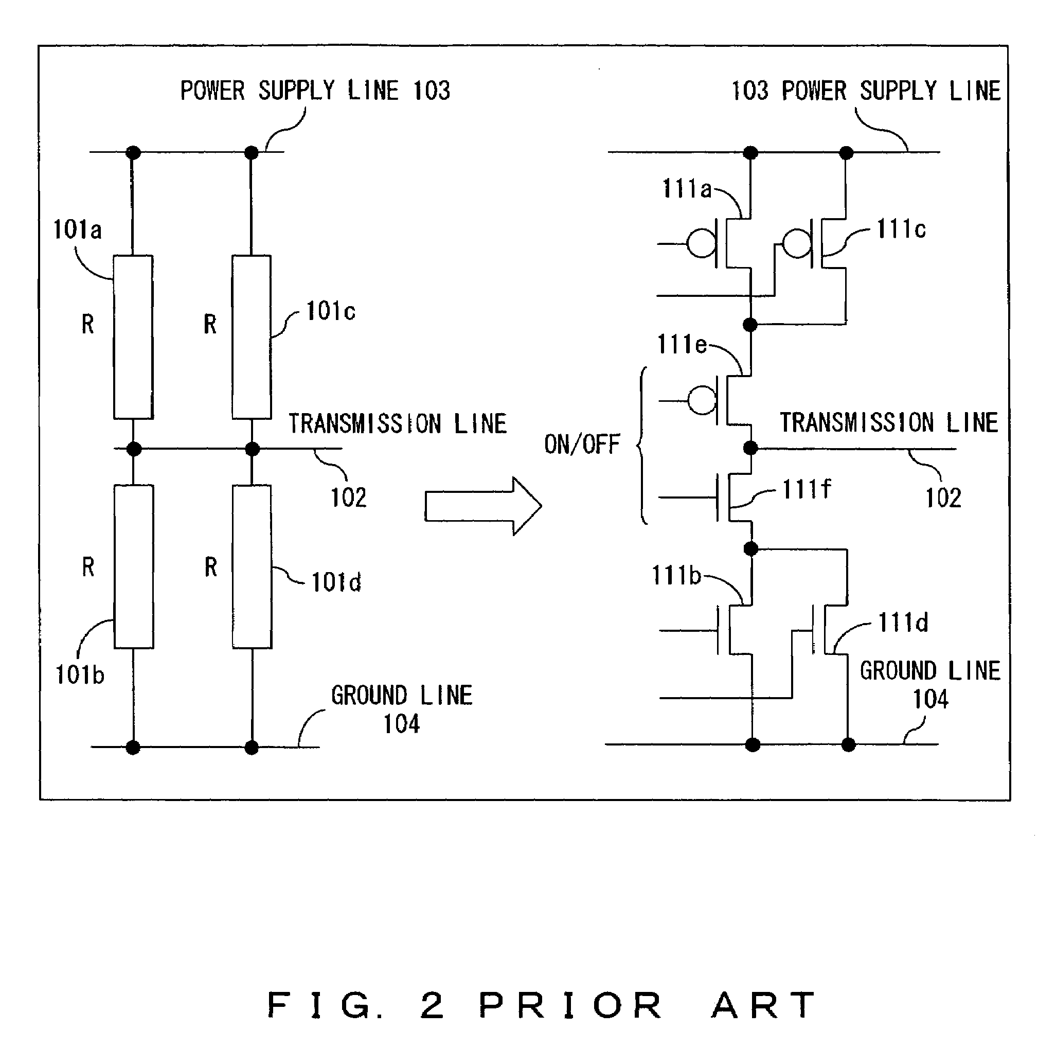
[0040]FIG. 3 shows the configuration of the termination circuit for implementing the present invention. In FIG. 3, the same reference numerals are attached to the same lines as in FIG. 2.

[0041]In this preferred embodiment, this termination circuit is formed on a single semiconductor substrate in a semiconductor device 1. This semiconductor device 1 is, for example, a central processing unit (CPU), and is provided for an electronic device 2, such as a computer or the like.

[0042]The termination circuit shown in FIG. 3 comprises a termination unit 10 for forming Thevenin termination and a control unit 40 for controlling both the switching of activation / inactivation of the terminal circuit and switching of a termination resistance value.

[0043]The termination unit 10 comprises both a first termination unit 10a and a second termination unit 10b for each transmission line 102. Althou...


PUM


Abstract

A termination circuit for terminating a transmission line comprises a resistance unit which is formed by connecting a P-channel type MOS transistor and an N-channel type MOS transistor in parallel, and Thevenin termination is formed by providing this resistance unit between the transmission line and a power supply line and between the transmission line and a ground line.

Description

BACKGROUND OF THE INVENTION[0001]1. Field of the Invention[0002]The present invention relates to a signal transmission technology, more particularly to a technology for a termination circuit for matching a plurality of segments of impedance of a transmission line.[0003]2. Description of the Related Art[0004]In a memory interface based on double data rate 2 (DDR2) rating stipulated by Joint Electron Device Engineering Council (JEDEC), it is required that a termination circuit should be provided on the controller side of memory.[0005]It is required that the termination circuit on the controller side in a DDR2 interface is activated when a controller receives data, and it is inactivated when the controller transmits data. It is stipulated that the matched impedance of a transmission line should be 75 ohms. Therefore, if a controller and memory are connected 1 to 1, the termination resistance value is made to be 75 ohms. However, if a controller and memory are connected 1 to 2, the term...

Claims


Application Information

Patent Timeline
Patent Type & Authority Patents(United States)
IPC IPC(8): H03K17/16
CPCH03K19/0005H04L25/0298
Inventor TOKUHIRO, NORIYUKIITOH, KUNIHIRO
Owner FUJITSU LTD
Why Eureka
Try Eureka