Method for producing a tube

a tube and substrate technology, applied in the direction of resistive material coating, separation process, instruments, etc., can solve the problems of complex assembly process, troublesome outgassing of systems constructed of such organic materials, and complex assembly process

Active Publication Date: 2007-01-02
NAT TECH & ENG SOLUTIONS OF SANDIA LLC
View PDF12 Cites 118 Cited by
  • Summary
  • Abstract
  • Description
  • Claims
  • Application Information

AI Technical Summary

Problems solved by technology

This approach provides a functional system albeit one that is not amenable to miniaturization or low cost of manufacture.
The use of brazing to join the piece parts would produce a relatively inert, non-contaminating drift tube but requires a complicated assembly process.
Systems constructed of such organic materials can be troubled with outgassing of contaminants from these materials, and may require extended flushing of the system to achieve optimum sensitivity.
This system provides for integrating the electronics near the drift tube, but again requires a complex assembly process.
Manufacture of such a device proved successful, but was labor intensive and prone to leakage, as is typical for a structure with a large number of joints, each required to be airtight.
While a method as taught by Muckelroy et al might provide a basis for developing a drift chamber, the requirement to print networks on the interior of a tube is difficult to manufacture, and necessarily restricts the process to tubular structures with a large inner diameter, to accommodate the screen printing means.
Kanai et al does not provide a method for interconnecting inner and outer electrodes as these ‘short-circuits’ would be deleterious to producing a capacitor, and is cited as a disadvantageous by-product of processes requiring accurate alignment of two green ceramic sheets.
Having to form the substrate while in the heated state unnecessarily complicates the process and exposes external conductor and resistor networks to potential damage during handling.
While this method can produce a channel in a planar substrate, ionizing of species and control of ion flow through appropriate application of an electric field gradient is not required for separation of gas species in Briscoe's disclosed method, and thus there is no provision for producing such.

Method used


Image

  • Method for producing a tube
  • Method for producing a tube
  • Method for producing a tube

Examples


Embodiment Construction

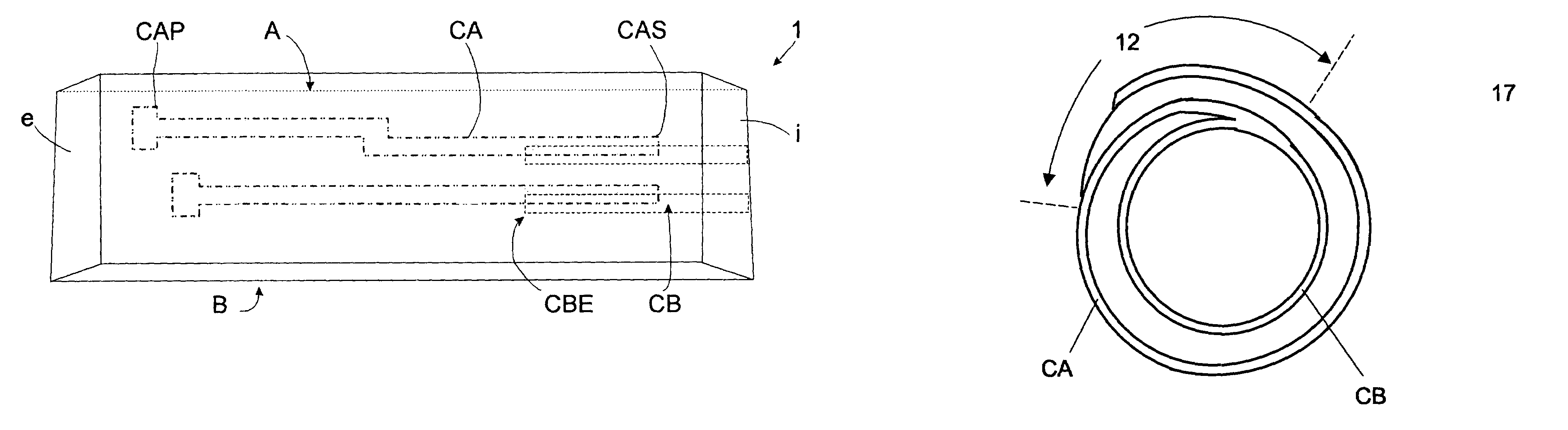
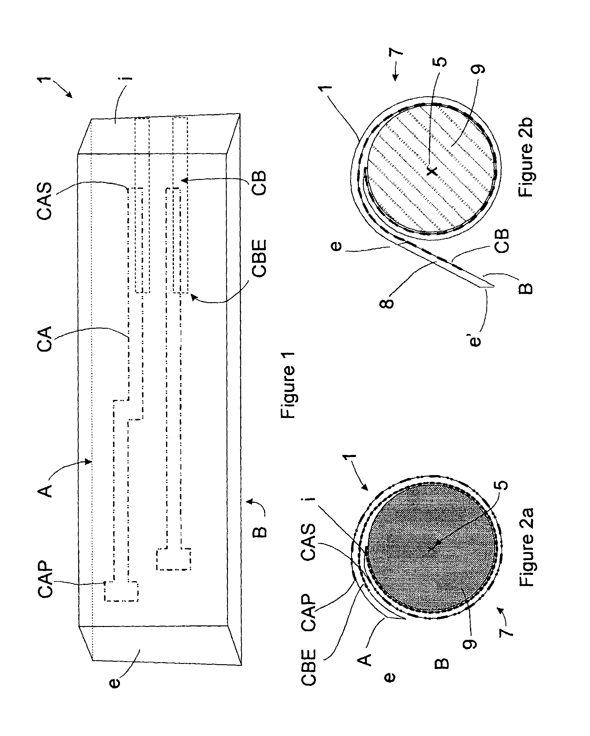
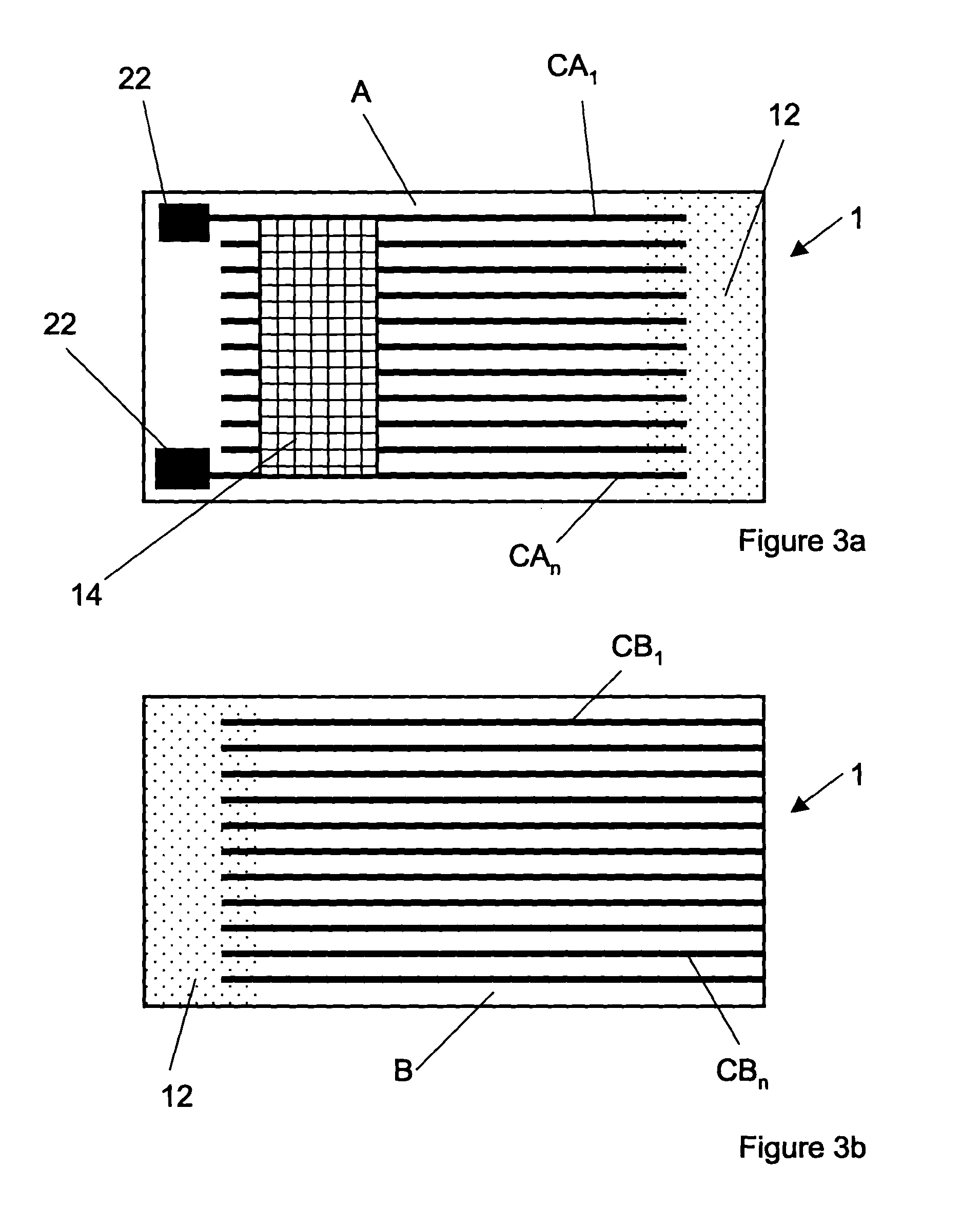
[0043]In accordance with a first embodiment of this invention, FIG. 1 shows a flexible substrate (1) having opposed surfaces (A) and (B) and opposed ends (i) and (e). As discussed hereinafter, flexible substrate (1) may have conductors (CA) and (CB) on the opposing surfaces. Although shown as one layer, flexible substrate (1) may be formed of multiple layers each of which may contain one of the electrodes (CA) and (CB). As shown in FIG. 2a, substrate (1) is intended to be formed into a tube (7) having an axis (5) which may be perpendicular to a line (not shown) extending between ends (i) and (e). As is well known in the art, tube (7) may be formed by coiling or rolling surface (B) and end (i) of substrate (1) around a mandrel (9) that may be subsequently removed. For simplicity, FIG. 2a shows tube (7) to be formed from about one and one sixth revolutions of substrate (1) around mandrel (9). The invention contemplates tube (7) being formed from multiple revolutions of substrate (1). ...


PUM

PropertyMeasurementUnit
temperaturesaaaaaaaaaa
included angleaaaaaaaaaa
temperatureaaaaaaaaaa

Abstract

A method is described for producing tubular substrates having parallel spaced concentric rings of electrical conductors that can be used as the drift tube of an Ion Mobility Spectrometer (IMS). The invention comprises providing electrodes on the inside of a tube that are electrically connected to the outside of the tube through conductors that extend between adjacent plies of substrate that are combined to form the tube. Tubular substrates are formed from flexible polymeric printed wiring board materials, ceramic materials and material compositions of glass and ceramic, commonly known as Low Temperature Co-Fired Ceramic (LTCC). The adjacent plies are sealed together around the electrode.

Description

CROSS REFERENCE TO RELATED APPLICATIONS[0001]This application claims the benefit of U.S. Provisional Application No. 60 / 408,801, filed on Sep. 5, 2002.STATEMENT REGARDING FEDERALLY SPONSORED RESEARCH OR DEVELOPMENT[0002]The United States Government has rights in this invention pursuant to Department of Energy Contract No. DE-AC04-94AL85000 with Sandia Corporation.BACKGROUND OF THE INVENTION[0003]This invention relates to tubular substrates having electrical conductors on an interior surface that are electrically connected through the tube wall to contacts on the tube exterior. Preferably, the conductors are concentric rings for a drift tube of an Ion Mobility Mass Spectrometer (IMS). This invention further relates to methods for producing such tubular substrates from flexible polymeric printed wiring board materials, ceramic materials and material compositions of glass and ceramic, commonly known as Low Temperature Co-Fired Ceramics (LTCC).[0004]In the context of the present inventi...

Claims


Application Information

Patent Timeline
Patent Type & Authority Patents(United States)
IPC IPC(8): H01C17/00
CPCH01C3/06H01C17/07Y10T29/49124Y10T29/49082Y10T29/4913Y10T29/49155Y10T29/49117
Inventor PETERSON, KENNETH A.ROHDE, STEVEN B.PFEIFER, KENT B.TURNER, TIMOTHY S.
Owner NAT TECH & ENG SOLUTIONS OF SANDIA LLC
Why Eureka
Try Eureka