High-speed liquid dispensing modules

Inactive Publication Date: 2007-01-02
NORDSON CORP
View PDF23 Cites 11 Cited by
  • Summary
  • Abstract
  • Description
  • Claims
  • Application Information

AI Technical Summary

Benefits of technology

[0011]The present invention provides apparatus and methods for dispensing a heated liquid. In accordance with the principles of the present invention, an apparatus for dispensing a liquid includes a liquid distribution manifold capable of heating the liquid, a dispenser body capable of receiving a flow of the liquid from said liquid distribution manifold, and a pneumatic actuator. The dispenser body is equipped with a flow-control mechanism having a first condition in which the flow of the liquid is discharged from the dispenser body and a second condition in which the flow of the liquid is blocked. The pneumatic actuator has a solenoid valve equipped with an air outlet, an air piston housing, an air cavity disposed

Problems solved by technology

If the heated liquid cools below a threshold temperature, it may not remain flowable and/or molten or may not have the desired properties when applied on the substrate.
If the operating temperature rises above a certain threshold temperature, the solenoid valve cannot operate properly and may malfunction, suffer permanent damage, or fail.
It follows that simply spacing the solenoid valve from the housing containing the air cavity with a nipple or a length of tubing is not an adequate solution for reducing the heating of the solenoid valve in tho

Method used


Image

  • High-speed liquid dispensing modules
  • High-speed liquid dispensing modules
  • High-speed liquid dispensing modules

Examples


Example

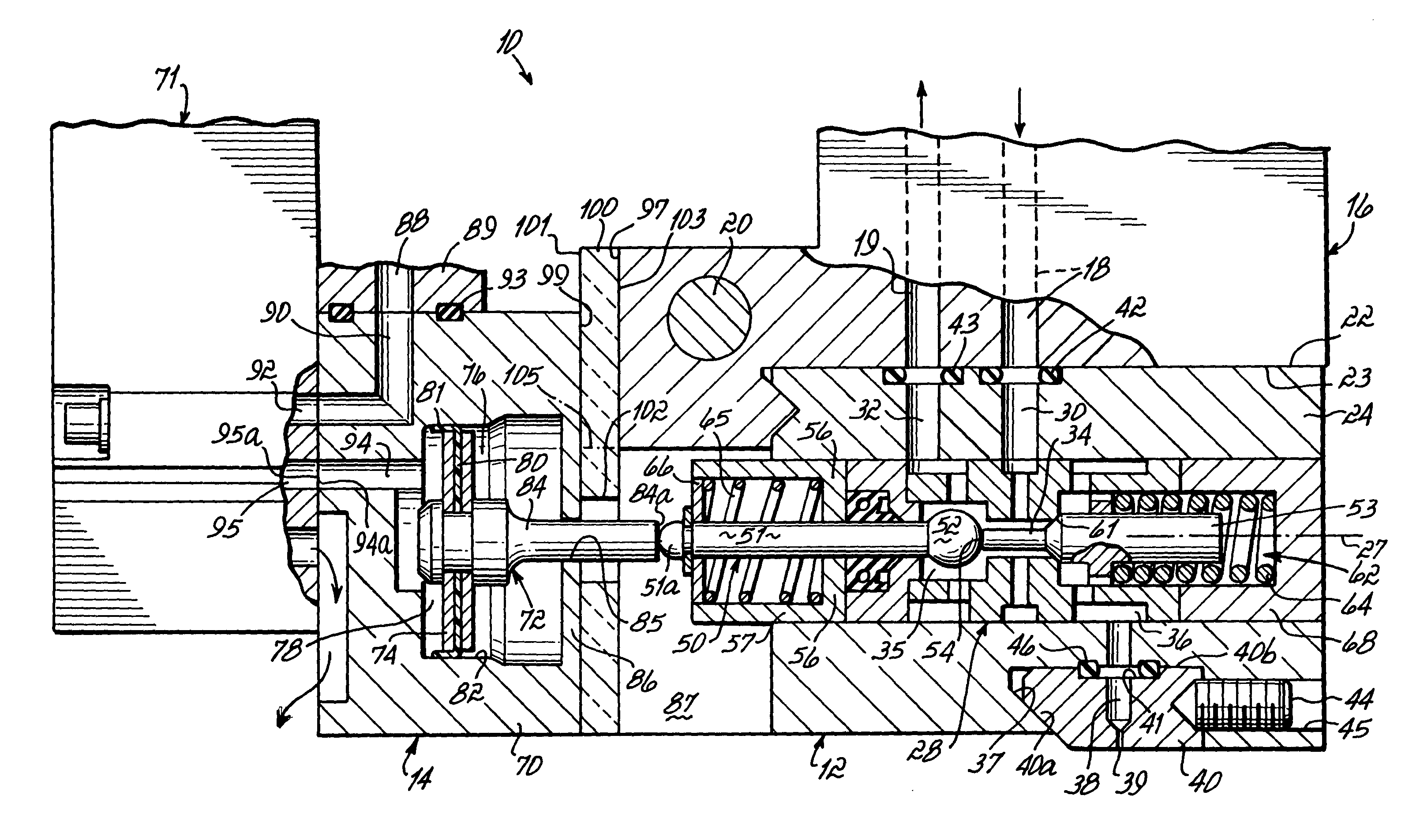
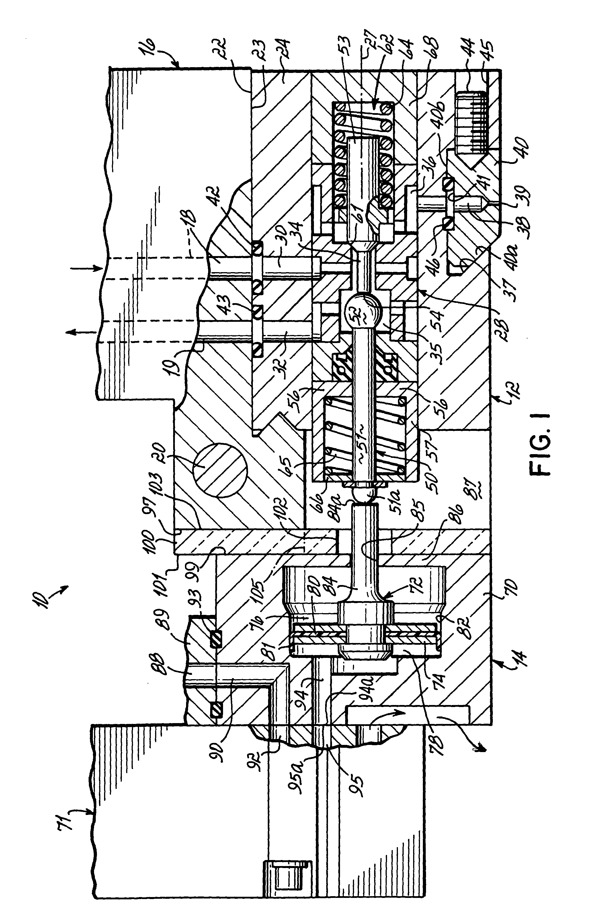
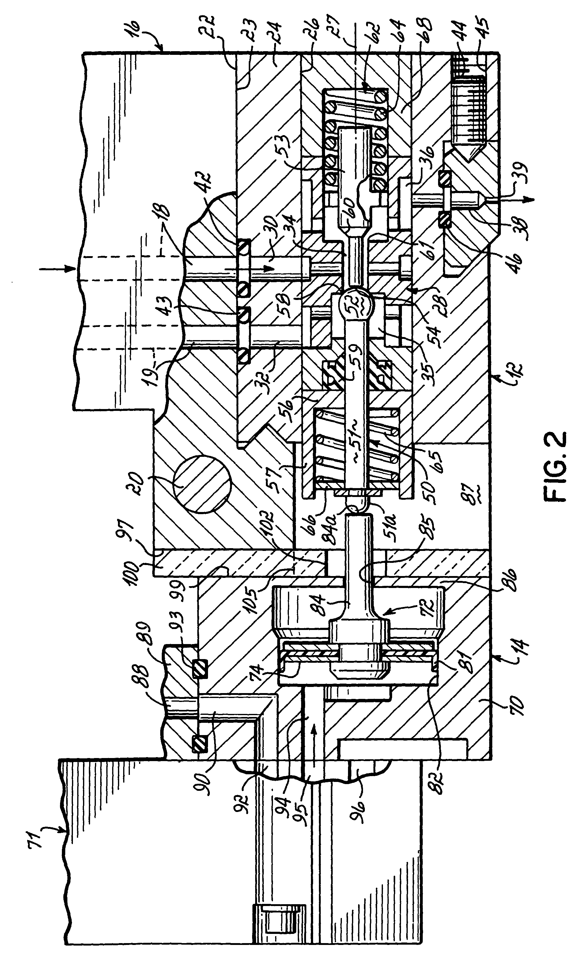
[0025]With reference to FIGS. 1 and 2, a liquid dispensing module 10 constructed in accordance with the principles of the present invention includes a dispenser body 12 and an actuator 14. The liquid dispensing module 10 is specifically adapted for dispensing a heated liquid, such as a molten thermoplastic hot melt adhesive. However, other heated liquid dispensing modules will also benefit from principles of the present invention. The liquid dispensing module 10 constitutes a flow control device adapted to accept a flow of a heated liquid and dispense the heated liquid in a controlled fashion onto a substrate. The liquid dispensing module 10 is configured to be actuated by the actuator 14 between an open position (FIG. 2), in which heated liquid is dispensed from the dispenser body 12, and a closed position (FIG. 1), in which the dispensing of heated liquid is halted.

[0026]The dispenser body 12 is mounted in a conventional manner to liquid distribution manifold 16. Liquid distributi...


PUM


Abstract

Liquid dispensing module and methods for dispensing a heated liquid onto a substrate. The dispensing module includes a dispenser body receiving liquid from a heated liquid distribution manifold and an actuator having a housing with an air piston movable in an air cavity and a solenoid valve for pressurizing the air cavity. Movement of the air piston controls a flow-regulating mechanism for selectively dispensing liquid from the dispenser body. A thermally insulating shield may be provided for reducing heat transfer from the manifold and/or dispenser body to the actuator so that the solenoid valve can be mounted directly to the housing and the effective volume of the air cavity can be reduced. The cycle time of the liquid dispensing module may be specified by selecting an initial volume of the air cavity and an effective valve flow coefficient for the actuator that characterizes the air flow to the air cavity.

Description

CROSS-REFERENCE TO RELATED APPLICATIONS[0001]This application is a divisional of application Ser. No. 09 / 999,243, filed Oct. 31, 2001, now U.S. Pat. No. 6,669,057, the disclosure of which is hereby fully incorporated by reference herein.FIELD OF THE INVENTION[0002]The present invention generally relates to liquid dispensing and, more particularly, to liquid dispensing modules for dispensing heated liquids onto a surface of a substrate.BACKGROUND OF THE INVENTION[0003]Various liquid dispensing modules have been developed for the precise application of a heated liquid, such as a thermoplastic hot melt adhesive, on a substrate. In many dispensing applications, the flow of heated liquid must be periodically interrupted to sharply delimit the leading and trailing edges of individual application zones in a pattern of heated liquid applied on the substrate. To that end, most liquid dispensing modules have an open position in which heated liquid is discharged and a closed position in which ...

Claims


Application Information

Patent Timeline
IPC IPC(8): B67D5/62B67D7/80B05C5/00B05C5/02B05C5/04B05C11/10
CPCB05C5/001B05C5/0237B05C5/0258Y10T436/2575B05C11/1042B05B15/65Y10T137/7036
Inventor SAIDMAN, LAURENCE B.SEEDORF, HANS JOACHIM
Owner NORDSON CORP
Why Eureka
Try Eureka