Interior rearview mirror assembly with polymeric components
a technology for rearview mirrors and components, applied in the direction of machine supports, couplings, other domestic objects, etc., can solve the problems of inability to adjust, difficult to maintain constant, consistent torque requirements for ball pivot joints, etc., and achieve the effect of improving performance and facilitating manufactur
- Summary
- Abstract
- Description
- Claims
- Application Information
AI Technical Summary
Benefits of technology
Problems solved by technology
Method used
Image
Examples
embodiment 10
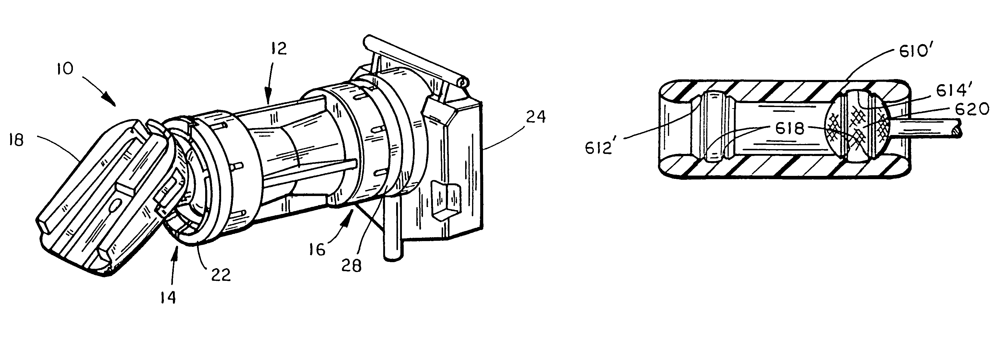
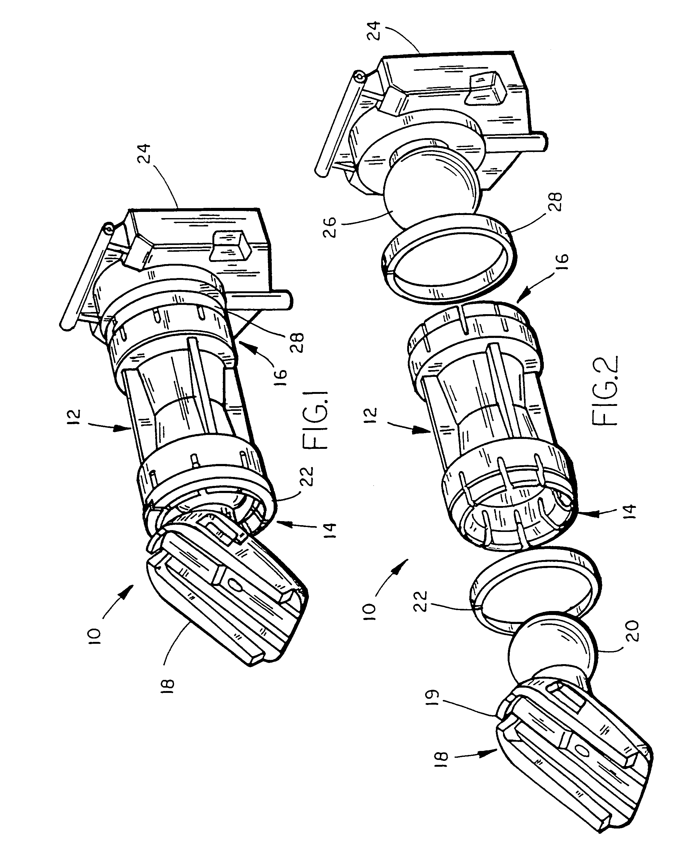
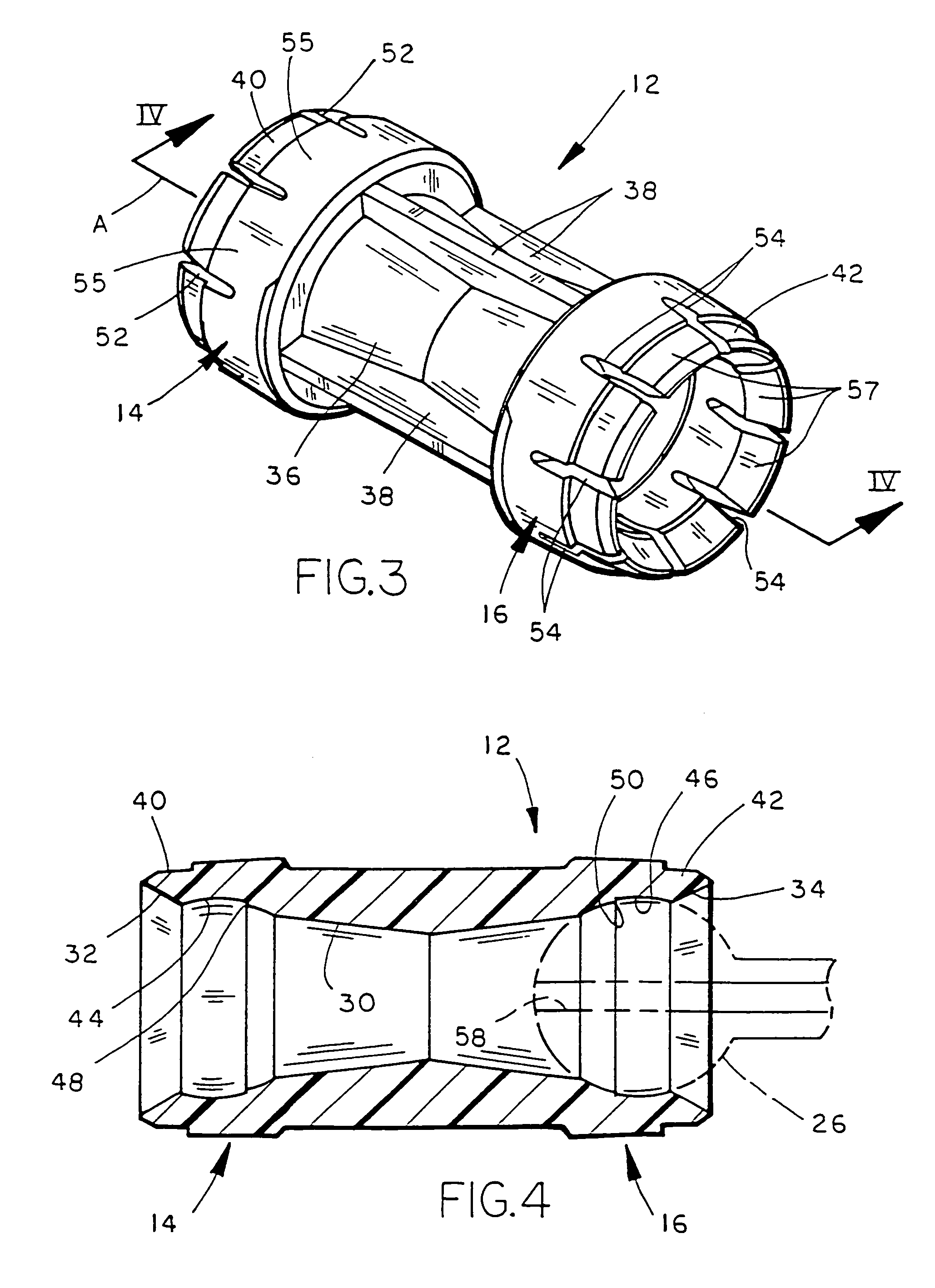
[0146]With reference to FIG. 6, an alternate embodiment 10′ of the rearview mirror support is shown which is similar in substantially all respects to embodiment 10 and wherein like numerals indicated like parts. However, support 10′ includes a modified sleeve 12′ which is tubular but has differing cross sections at the central and end portions. More specifically, sleeve 12′ includes a central section 60 having a lateral exterior dimension of a predetermined size measured transverse to the central axis which is preferably larger than that of sleeve 12 and provides an interior space 61 which may be used to house or support other vehicle accessories as described below. In addition, sleeve 12′ includes recessed opposing ends 62, 64 which may be of the same or differing lateral exterior dimension as compared to one another. Preferably, sleeve 12′ is circular in section such that the dimensions of sections 60, 62, and 64 are diameters. Alternately, the sleeve may have varying sectional sh...
embodiment 600
[0153]As shown in FIG. 46, a further embodiment 600 of the rearview mirror support (that is preferably formed of a polymeric resin such as by injection molding) of the present invention is shown including a modified continuous sleeve 602 including a socket 604 adjacent one end for receiving a ball pivot member preferably compression fitted therein for an interference fit within the socket as described above, and a socket 606 at the other end for similarly receiving a ball pivot member from a rearview mirror assembly component as shown in phantom. Preferably, as shown in FIG. 46, sockets 604, 606 each have a cross-sectional shape which is slightly different from that of a generally spherical ball pivot member. The diameter of sleeve 602 at left end 602a is larger than the diameter of end 602b such that that the wall thickness of the tube adjacent socket 604 is greater than the wall thickness adjacent socket 606. This provides a difference in torque or frictional resistance to pivotal...
embodiment 630
[0159]With reference to FIG. 50, a further embodiment 630 of the rearview mirror support of the present invention includes a molded plastic, rectilinear, cylindrical sleeve or tube 631 having a socket 632 at the windshield or channel mount end and a socket 634 at the mirror assembly end. Sockets 632, 634 are designed to receive ball pivot members therein with an interference fit and a desired frictional resistance to pivotal movement using one or more of the methods described above. In addition, sleeve 631 includes a vibration reducing or dampening element inserted or incorporated in the tube such as a cork, foam (such as polystyrene foam), thermoplastic elastomer, or urethane dampening plug or member 636 press-fitted within the inner diameter of the tube or adhered therein centrally between sockets 632, 634 with a suitable adhesive and / or mechanically. Alternately, dampening member 636 could be co-injected with sleeve 631 from the same or a different material rather than separatel...
PUM
 Abstract
Description
Claims
Application Information
 - R&D
- Intellectual Property
- Life Sciences
- Materials
- Tech Scout
- Unparalleled Data Quality
- Higher Quality Content
- 60% Fewer Hallucinations
Browse by: Latest US Patents, China's latest patents, Technical Efficacy Thesaurus, Application Domain, Technology Topic, Popular Technical Reports.
© 2025 PatSnap. All rights reserved.Legal|Privacy policy|Modern Slavery Act Transparency Statement|Sitemap|About US| Contact US: help@patsnap.com


