
Rod reduction nut and driver tool

a technology of driver tool and rod, which is applied in the direction of ligaments, prostheses, osteosynthesis devices, etc., can solve the problems of difficult alignment and seating of rods into the rod receiving portion of adjacent fixation devices, and the difficulty of mounting rods into the rod-receiving portion of various fixation devices,

Inactive Publication Date: 2007-01-02
DEPUY ACROMED INC
View PDF27 Cites 110 Cited by
  • Summary
  • Abstract
  • Description
  • Claims
  • Application Information

AI Technical Summary

Benefits of technology

[0006]The present invention generally provides a rod reduction device for reducing a rod disposed within a rod-receiving recess formed in a rod-receiving head of a spinal implant. The rod reduction device includes a reduction nut having a proximal end, a distal end, and a sidewall extending therebetween defining inner and outer surfaces. Threads are formed on the inner surface of the reduction nut adjacent to the distal end. The device further includes a driver tool having an elongate shaft with proximal and distal ends. The distal end is sized to engage the reduction nut such that rotation of the driver tool is effective to rotate the reduction nut to thread the nut onto the rod-receiving head of a spinal implant to reduce a rod disposed therein. The driver tool can also include a support member adapted to be positioned within the rod-receiving head of the spinal implant to prevent the head from collapsing inward during reduction of the rod. The support member can be, for example, a hollow cylindrical tube formed on a distal-most end of the driver tool and having an outer diameter less than an inner diameter of the reduction nut.

Problems solved by technology

While current spinal fixation systems have proven effective, difficulties have been encountered in mounting rods into the rod-receiving portion of various fixation devices.
In particular, it can be difficult to align and seat the rod into the rod receiving portion of adjacent fixation devices due to the positioning and rigidity of the vertebra into which the fixation device is mounted.
While several rod approximators are known in the art, some tend to be difficult and very time-consuming to use.

Method used


Image

  • Rod reduction nut and driver tool
  • Rod reduction nut and driver tool
  • Rod reduction nut and driver tool

Examples


Embodiment Construction

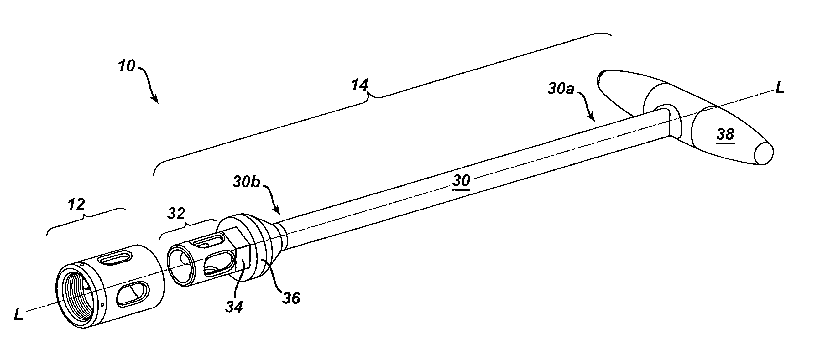
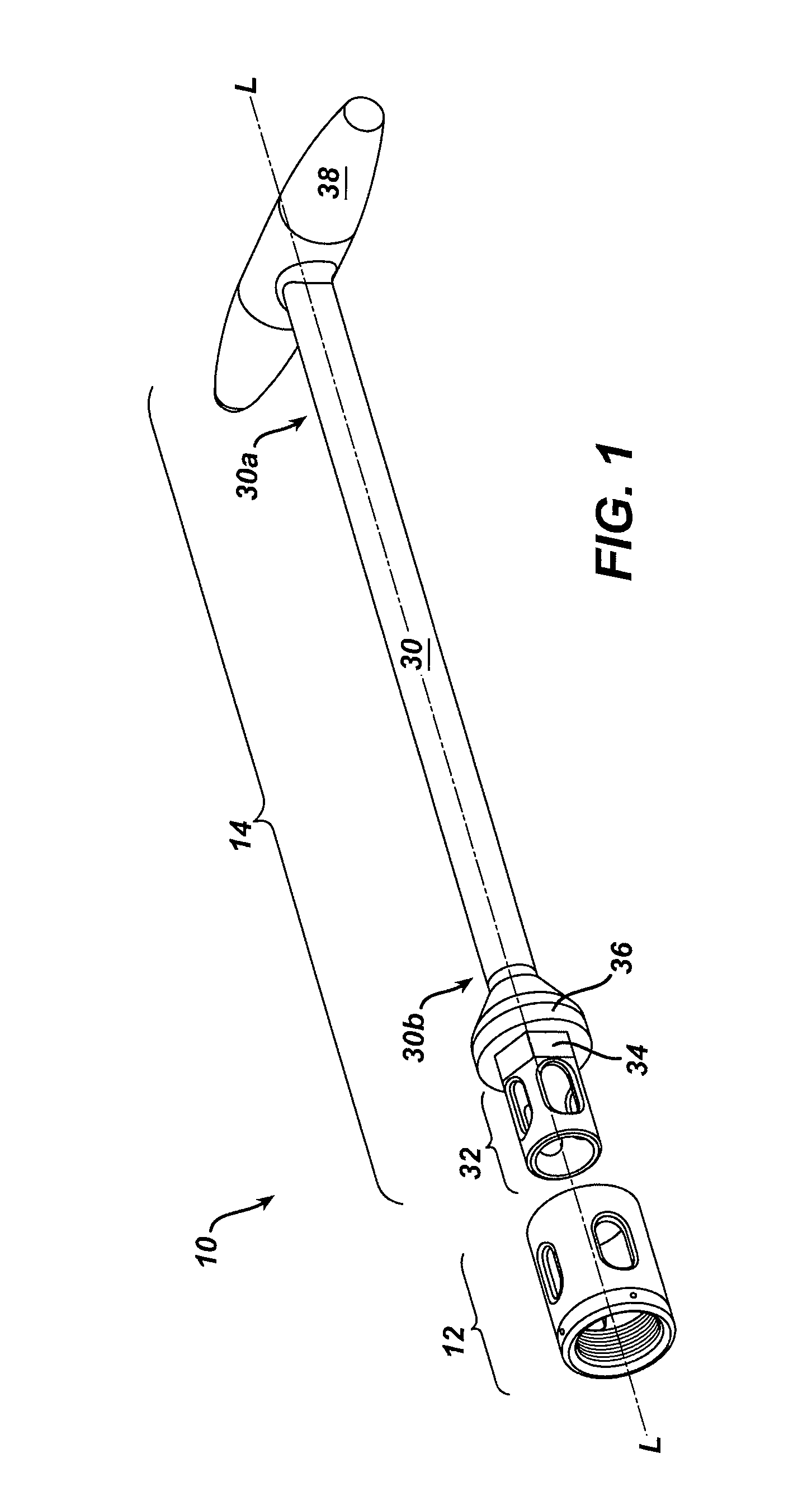
[0022]As shown in FIG. 1, the present invention generally provides a rod reduction device 10 having a reduction nut 12 adapted to mate to the rod-receiving portion of a spinal implant, and a driver tool 14 that is effective to engage the reduction nut 12 such that rotation of the driver tool 14 rotates the reduction nut 12 to reduce a rod positioned between the reduction nut 12 and within the rod-receiving head of a spinal implant into the rod-seating portion of the head of the spinal implant. The driver tool 14 can also include a support member 32 formed on a distal end 30b thereof that is adapted to be disposed within the rod-receiving head of a spinal implant to prevent the rod-receiving head of the implant from collapsing during use of the rod reduction device 10. The device 10 is particularly advantageous in that it provides a mechanical mechanism for reducing a rod, thereby allowing a closure mechanism to be easily mated to the implant to secure the rod therein. The device is ...


PUM


Abstract

A rod reduction device is provided having a reduction nut adapted to mate to the rod-receiving portion of a spinal implant, and a driver tool that is effective to engage the reduction nut such that rotation of the driver tool rotates the reduction nut to reduce a rod positioned between the reduction nut and within the rod-receiving head of a spinal implant into the rod-seating portion of the head of the spinal implant. The driver tool can include a support 32 formed on a distal end thereof that is adapted to be disposed within the rod-receiving head of a spinal implant to prevent the rod-receiving head of the implant from collapsing during use of the rod reduction device.

Description

FIELD OF THE INVENTION[0001]The present invention relates to spinal fixation systems, and in particular to spinal rod reduction devices, spinal implants, and methods for using the same.BACKGROUND OF THE INVENTION[0002]Spinal fixation devices are used in orthopedic surgery to align and / or fix a desired relationship between adjacent vertebral bodies. Such devices typically include a spinal fixation element, such as a relatively rigid fixation rod, that is coupled to adjacent vertebrae by attaching the element to various anchoring devices, such as hooks, bolts, wires, or screws. The fixation rods can have a predetermined contour that has been designed according to the properties of the target implantation site, and once installed, the instrument holds the vertebrae in a desired spatial relationship, either until desired healing or spinal fusion has taken place, or for some longer period of time.[0003]Spinal fixation devices can be anchored to specific portions of the vertebra. Since ea...

Claims


Application Information

Patent Timeline
IPC IPC(8): A61B17/56A61B17/70A61B17/88A61B19/00A61F2/46
CPCA61B17/7091A61F2/4611A61B17/7037A61F2002/4623A61B2019/307A61F2/4603A61B2090/037
Inventor DUNBAR, WILLIAM L.RYBICKI, CHRISBURGESS, IANSACHER, RON
Owner DEPUY ACROMED INC
Features
  • Generate Ideas
  • Intellectual Property
  • Life Sciences
  • Materials
  • Tech Scout
  • Unparalleled Data Quality
  • Higher Quality Content
  • 60% Fewer Hallucinations
Learn More