Process for treating industrial effluent water with activated media

a technology of activated media and industrial effluent, which is applied in the nature of treatment water, biological water/sewage treatment, separation process, etc., can solve the problems of inability to treat waste streams by known biological treatment processes, inability to treat effluent water streams containing inorganic and organic contaminants, and sometimes contaminated water reservoirs. to achieve the effect of reducing residues requiring disposal

Active Publication Date: 2009-02-17
AGUA DULCE TREATMENT SYST LLC
View PDF25 Cites 13 Cited by
  • Summary
  • Abstract
  • Description
  • Claims
  • Application Information

AI Technical Summary

Benefits of technology

[0008]In accordance with the invention, a process and apparatus are provided for treating effluent water from oil field and industrial facilities with activated media such as porous ceramics so as to reduce residues requiring disposal from treatment operations sufficiently to allow discharge of the effluent water to the sea directly or to recycle the effluent water for other purposes without incurring the disadvantage of generating a solid sludge.

Problems solved by technology

Similarly, chemical and industrial processes use water in their operations for cooling, quenching, pH adjustment and washing of various hydrocarbon streams, usually resulting in the creation of an effluent water stream containing inorganic and organic contaminants.
Tank farm operations, marine facilities and ships contain effluent water and soil and ground water reservoirs are occasionally contaminated by oil and chemical spills.
High concentrations of toxic and organic substances such as cyanide, arsenic, and heavy metal ions and solutions such as copper, lead and zinc inhibit enzyme formation in the microorganisms and eventually kill them.
Consequently, some waste streams are not treatable by known biological treatment processes.
Most problematic is that process pressure must be maintained between 300-3000 psig to prevent excessive evaporation of liquid.
Known chemical oxidation processes involve a relatively high operating cost and the chemicals used are consumed in the process.

Method used


Image

  • Process for treating industrial effluent water with activated media
  • Process for treating industrial effluent water with activated media
  • Process for treating industrial effluent water with activated media

Examples


Embodiment Construction

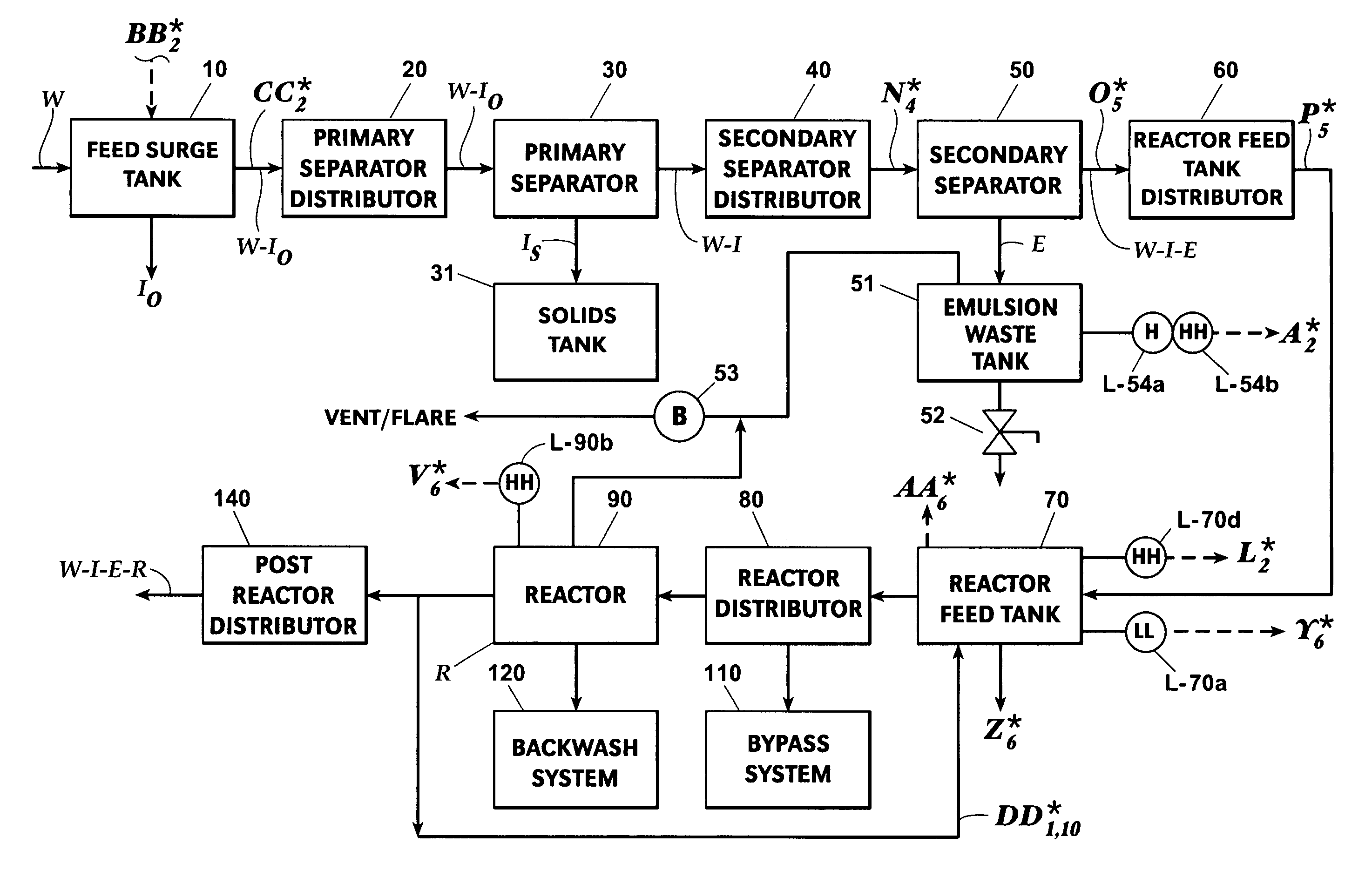
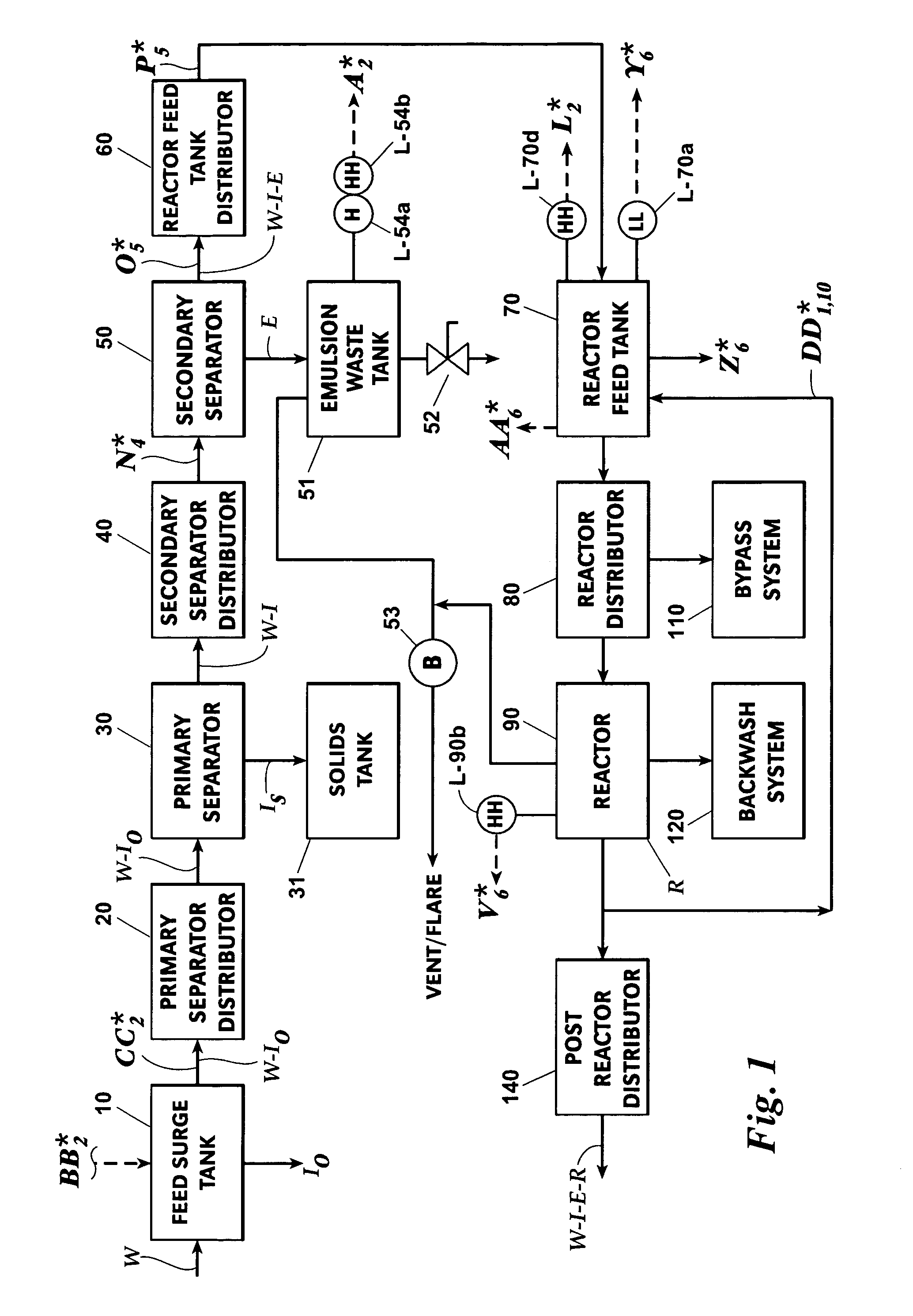
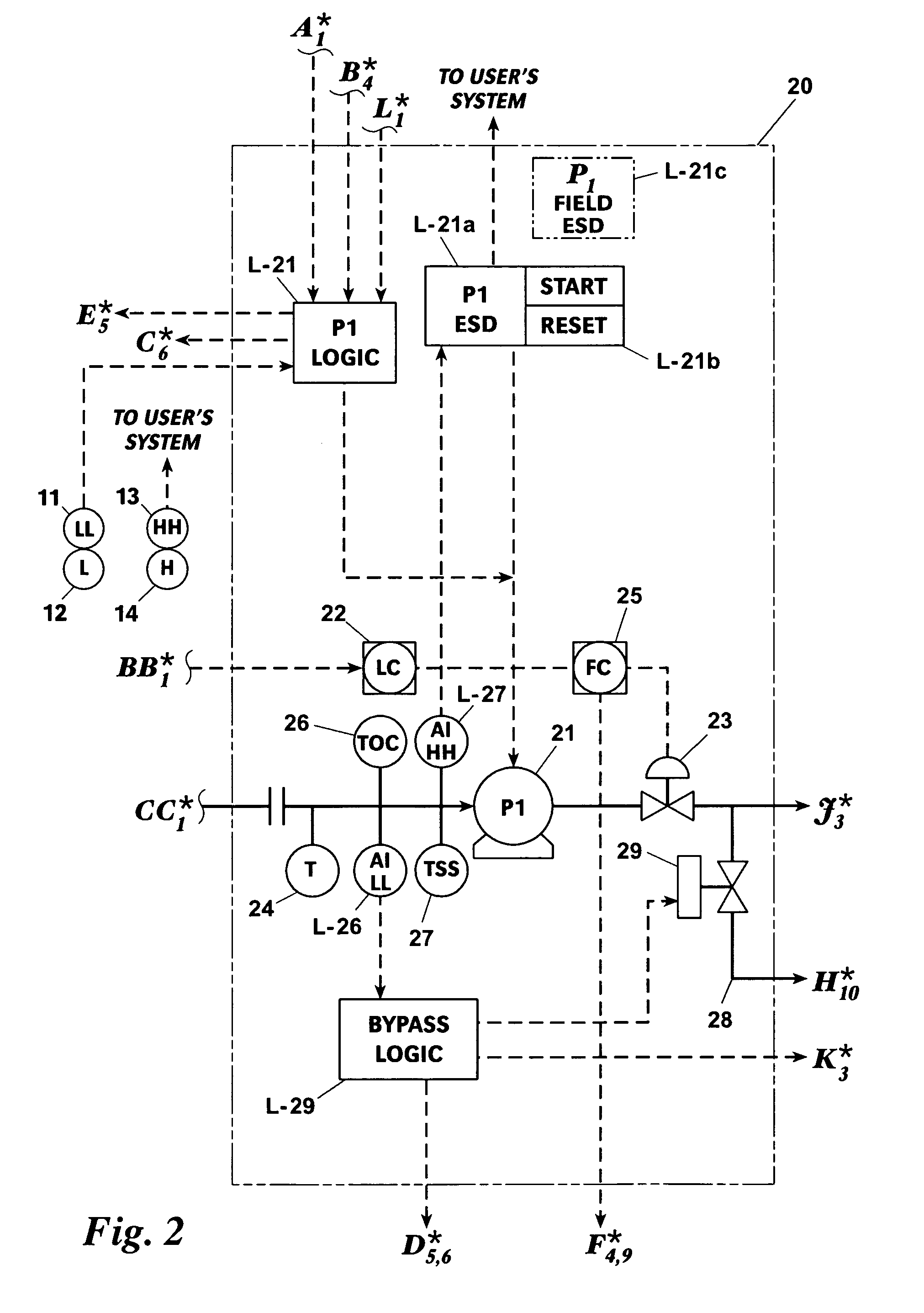
[0025]In the description, some flow lines connect system components which are illustrated in different Figures. Such flow lines have been identified by one or more capital letters with a superscripted asterisk and a subscript number. Each letter with superscripted asterisk indicates a particular flow line. The subscript indicates the other Figure associated with the flow line. For example, looking at FIG. 2, the identifier H10* is used with respect to the flow path from the output of a valve 29. Turning to FIG. 10, as indicated by the subscript in FIG. 2, the identifier H2* continues the H* flow path to the output of another valve 142. Conversely, continuing to look at FIG. 10, the subscript of the identifier H2* indicates that the other end of the flow line H* will be found in FIG. 2.

The System

[0026]Turning first to FIG. 1, a system for treating effluent water W discharged from oil field and industrial facilities includes a primary separator 30 for removing insoluble oil components...


PUM

PropertyMeasurementUnit
temperaturesaaaaaaaaaa
pressureaaaaaaaaaa
particle sizeaaaaaaaaaa

Abstract

In a process for treating effluent water, a stream of effluent water is fed to a porous ceramic media filled reactor. Organic and inorganic impurities are absorbed and / or oxidized from the effluent water into the media and / or off-gases. The remainder of the effluent water stream is dispensed from the reactor in an outlet stream suitable for direct discharge to the sea or for recycling without incurring the disadvantages of generating a solid sludge. The reactor includes a chamber containing activated media, such as pellets of porous ceramic material. The pellets are stored in a vertical stacks of sub chambers defined by horizontal perforated trays and / or in a horizontal chains of sub chambers defined by vertical perforated baffles.

Description

BACKGROUND OF THE INVENTION[0001]This invention relates generally to waste water treatment and more particularly concerns the treatment of hazardous waste waters such as the effluent water discharged from hydrocarbon processing facilities, general industrial facilities or contaminated municipal water supplies.[0002]The effluent water discharging from a hydrocarbon processing facility contains oil components, phenols, gas components such as H2S and NH3. Similarly, chemical and industrial processes use water in their operations for cooling, quenching, pH adjustment and washing of various hydrocarbon streams, usually resulting in the creation of an effluent water stream containing inorganic and organic contaminants. Tank farm operations, marine facilities and ships contain effluent water and soil and ground water reservoirs are occasionally contaminated by oil and chemical spills.[0003]The Federal Resource Conservation and Recovery Act (RCRA) of 1976 has focused the attention of both i...

Claims


Application Information

Patent Timeline
Patent Type & Authority Patents(United States)
IPC IPC(8): C02F3/00
CPCC02F1/281B03D1/24C02F1/40C02F1/74C02F2101/325C02F2103/36C02F2209/005C02F2209/10C02F2209/20C02F2209/40B03D1/028
Inventor MARKHAM, GARY W.KIRKPATRICK, HARMON L.GUERCIO, RICKMAST, DOUGLAS E.GUSTAS, JR., STANLEY C.
Owner AGUA DULCE TREATMENT SYST LLC
Why Eureka
Try Eureka