Antenna module and communication device

a technology of communication device and antenna module, which is applied in the direction of polarised antenna unit combination, individual energised antenna array, particular array feeding system, etc., can solve the problems of restricted so as to improve antenna characteristics, reduce the thickness of communication device, and improve the effect of antenna characteristics

Active Publication Date: 2020-04-16
MURATA MFG CO LTD
View PDF4 Cites 14 Cited by
  • Summary
  • Abstract
  • Description
  • Claims
  • Application Information

AI Technical Summary

Benefits of technology

[0029]With the above structure, the width of the second flat plate portion of the antenna module is decreased, and the second flat plate portion is disposed parallel to a side surface of an end portion of a mounting substrate (or a housing) of the communication device. Accordingly, the antenna characteristics can be improved, and the thickness of the communication device can be decreased.
[0030]An antenna module and a communication device according to the present disclosure have improved antenna characteristics and enable the thickness of the communication device on which the antenna module is disposed to be decreased.

Problems solved by technology

For this reason, in the case where the form of the antenna is selected such that priority is placed on antenna characteristics, and the 3D antenna system is mounted on a side surface of a communication device, there is a problem in that decrease in the thickness of the communication device is restricted because of the size of the antenna.
In this case, the decrease in the thickness of the communication device is restricted because of the size of the other flat surface.

Method used


Image

  • Antenna module and communication device
  • Antenna module and communication device
  • Antenna module and communication device

Examples


first embodiment

[0050][1.1 Structure of Antenna Module]

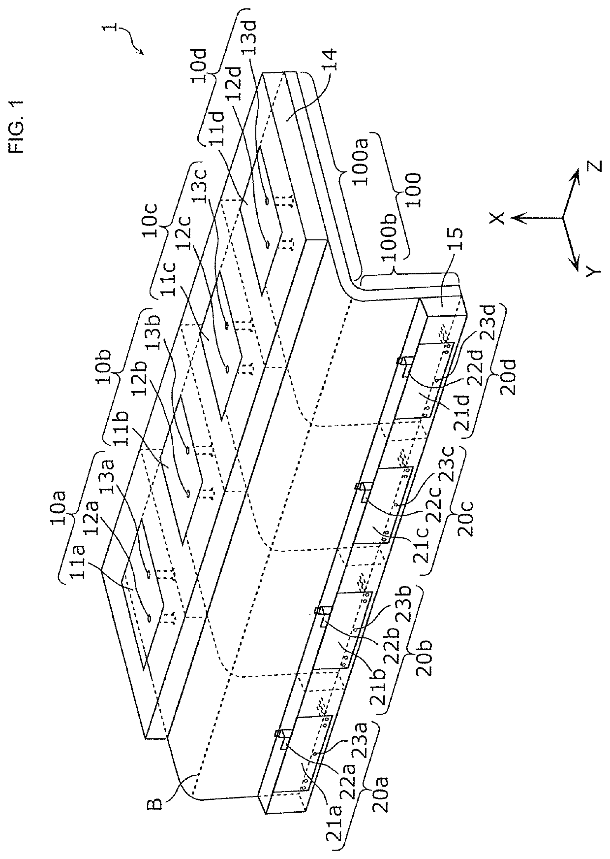
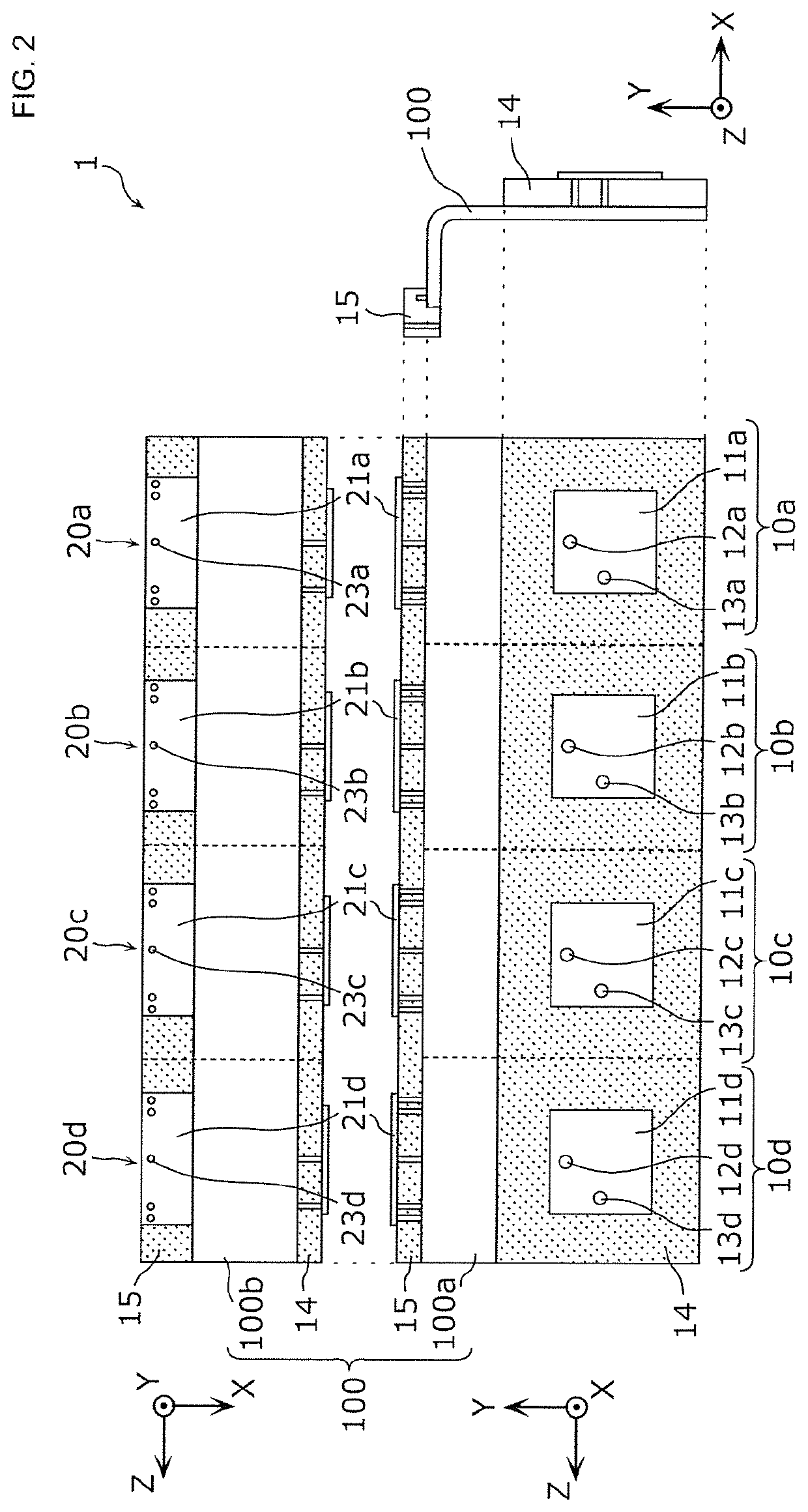
[0051]FIG. 1 is a perspective view of the appearance of an antenna module 1 according to a first embodiment. FIG. 2 illustrates three views (a front view, a plan view, and a side view) of the shape of the antenna module 1 according to the first embodiment.

[0052]As illustrated in FIG. 1, the antenna module 1 according to the present embodiment includes a substrate 100, first patch antennas 10a, 10b, 10c, and 10d, and second patch antennas 20a, 20b, 20c, and 20d.

[0053]The substrate 100 includes a first flat plate portion 100a and a second flat plate portion 100b that have respective normals intersecting with each other and that are continuous. According to the present embodiment, the substrate 100 has an L-shape in which the first flat plate portion 100a and the second flat plate portion 100b are folded about 90 degrees along a boundary line B.

[0054]The first patch antennas 10a to 10d are formed on the first flat plate portion 100a and arranged ...

second embodiment

[0112][2.1 Structure of Antenna Module]

[0113]According to the present embodiment, a structure for compensating the polarization direction of the second patch antennas of the antenna module 1 according to the first embodiment will be described.

[0114]FIG. 7 illustrates three views (a front view, a plan view, and a side view) of the shape of an antenna module 2 according to a second embodiment.

[0115]As illustrated in FIG. 7, the antenna module 2 according to the present embodiment includes the substrate 100, the first patch antennas 10a, 10b, 10c, and 10d, the second patch antennas 20a, 20b, 20c, and 20d, and notch antennas 30a, 30b, 30c, and 30d. The antenna module 2 according to the present embodiment differs from the antenna module 1 according to the first embodiment in including the notch antennas 30a to 30d. Differences between the antenna module 2 according to the present embodiment and the antenna module 1 according to the first embodiment will be mainly described, and the same ...


PUM


Abstract

An antenna module (1) includes a substrate (100) including a first flat plate portion (100a) and a second flat plate portion (100b) that have respective normals intersecting with each other and that are continuous, first patch antennas (10a to 10d) that are formed on the first flat plate portion (100a) and second patch antennas (20a to 20d) that are formed on the second flat plate portion (100b). The first patch antennas (10a to 10d) are arranged in at least a column in a column direction parallel to a boundary line (B) between the first flat plate portion (100a) and the second flat plate portion (100b). The second patch antennas (20a to 20d) are arranged in at least a column in the column direction.

Description

[0001]This is a continuation of International Application No. PCT / JP2018 / 022090 filed on Jun. 8, 2018 which claims priority from Japanese Patent Application No. 2017-117242 filed on Jun. 14, 2017. The contents of these applications are incorporated herein by reference in their entireties.BACKGROUND OF THE DISCLOSUREField of the Disclosure[0002]The present disclosure relates to an antenna module and a communication device.Description of the Related Art[0003]The structure of a 3D antenna system that includes patch antennas that serve as array antennas for wireless communication and that are arranged on two different flat surfaces is disclosed (see, for example, Patent Document 1). With this structure, directivity can have plural values, and the coverage of antenna radiation and reception can be improved.[0004]Patent Document 1: Japanese Unexamined Patent Application Publication (Translation of PCT Application) No. 2014-529971BRIEF SUMMARY OF THE DISCLOSURE[0005]For the 3D antenna syst...

Claims


Application Information

Patent Timeline
Patent Type & Authority Applications(United States)
IPC IPC(8): H01Q21/00H01Q9/04H01Q21/06H01Q21/24H04B1/18
CPCH01Q21/0025H04B1/18H01Q21/065H01Q9/0421H01Q21/245H01Q1/243H01Q9/0414H01Q9/16H01Q21/0075H01Q21/062H01Q25/00
Inventor TAKAYAMA, KEISEIONAKA, KENGOMORI, HIROTSUGUUOZUMI, SATOSHI
Owner MURATA MFG CO LTD
Why Eureka
Try Eureka